Table
5-2:
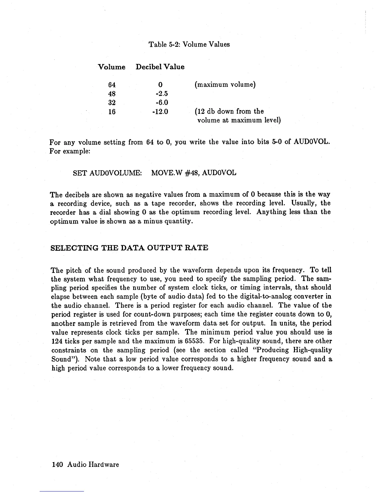
Volume Values
Volume
Decibel
Value
64
0
(maximum volume)
48
-2.5
32
-6.0
16
-12.0
(12
db down from the
volume
at
maximum level)
For
any volume setting from
64
to 0, you write the value into bits 5-0 of
AUDOVOL.
For example:
SET
AUDOVOLUME:
MOVE.W
#48,
AUDOVOL
The
decibels are shown as negative values from a maximum of 0 because this is the way
a recording device, such as a tape recorder, shows the recording level. Usually, the
recorder has a dial showing 0 as the optimum recording level. Anything less than the
optimum value is shown as a minus quantity.
SELECTING
THE
DATA
OUTPUT
RATE
The
pitch of the sound produced by the waveform depends upon its frequency.
To
tell
the system what frequency to use, you need
to
specify the sampling period.
The
sam-
pling period specifies the number of system clock ticks, or timing intervals,
that
should
elapse between each sample (byte of audio data)
fed
to
the digital-to-analog converter
in
the audio channel. There
is
a period register for each audio channel.
The
value of the
period register
is
used for count-down purposes; each time the register counts down to 0,
another sample
is
retrieved from the waveform
data
set for output. In units, the period
value represents clock ticks per sample.
The
minimum period value you should use
is
124 ticks per sample and the maximum
is
65535. For high-quality sound, there are other
constraints on the sampling period (see the section called "Producing High-quality
Sound "). Note
that
a
low
period value corresponds to a higher frequency sound and a
high period value corresponds to a lower frequency sound.
140 Audio Hardware