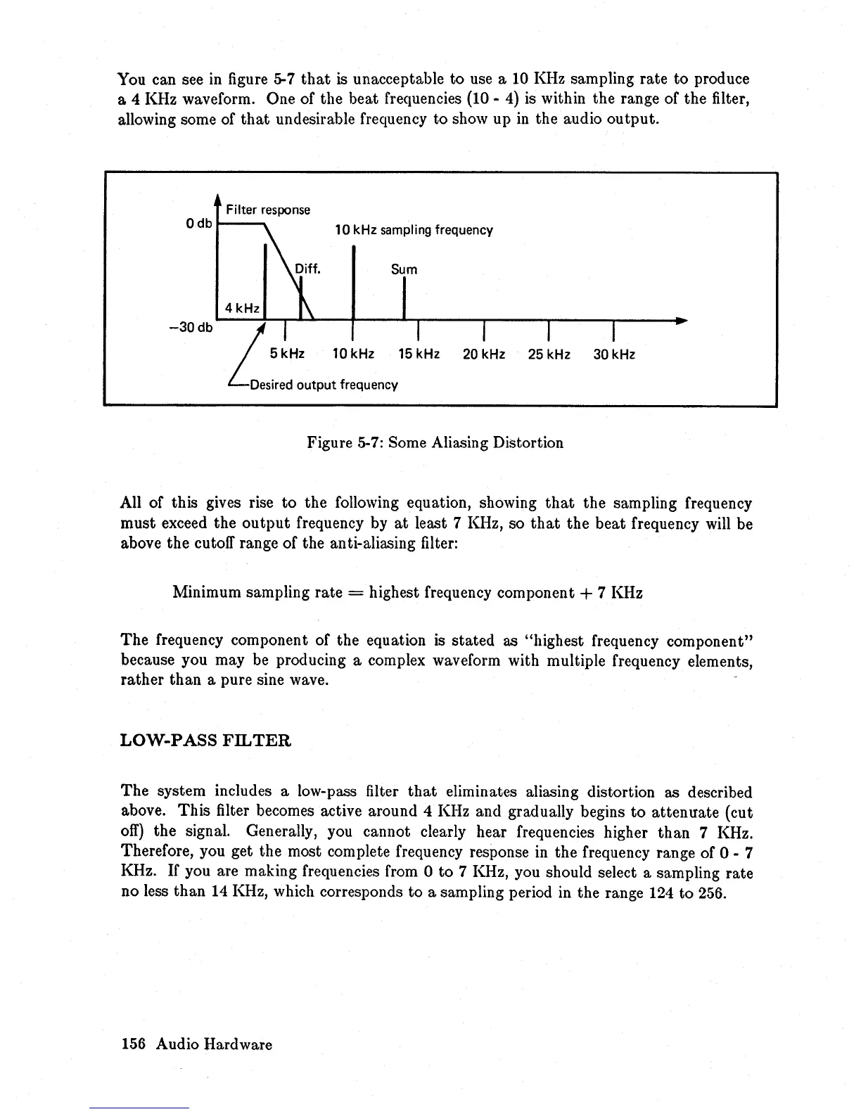
You can see in figure 5-7
that
is
unacceptable
to
use a 10 KHz sampling
rate
to
produce
a 4 KHz waveform. One of the beat frequencies (10 -
4)
is within the range of the filter,
allowing some of
that
undesirable frequency
to
show up
in
the audio
output.
Filter
response
Odb
~;ff'
10 kHz sampling frequency
Sum
4kHz
1\
-30
db
LI
I
I
I
I
5 kHz 10 kHz 15 kHz
20 kHz 25 kHz 30 kHz
Desired
output frequency
Figure 5-7: Some Aliasing Distortion
All of this gives rise
to
the following equation, showing
that
the sampling frequency
must exceed the
output
frequency by
at
least 7 KHz, so
that
the
beat
frequency will be
above the cutoff range of the anti-aliasing filter:
Minimum sampling rate
= highest frequency component + 7 KHz
The
frequency component of the equation is stated as "highest frequency component"
because you may be producing a complex waveform with multiple frequency elements,
rather
than
a pure sine wave.
LOW-PASS
FILTER
The
system includes a low-pass filter
that
eliminates aliasing distortion as described
above.
This
filter becomes active around 4 KHz and gradually begins
to
attenuate
(cut
off)
the signal. Generally, you cannot clearly hear frequencies higher
than
7 KHz.
Therefore, you get the most complete frequency response in the frequency range of 0 - 7
KHz.
If
you are making frequencies from 0
to
7 KHz, you should select a sampling
rate
no less
than
14
KHz, which corresponds
to
a sampling period in the range 124
to
256.
156 Audio Hardware