Blitter
Block
Diagram
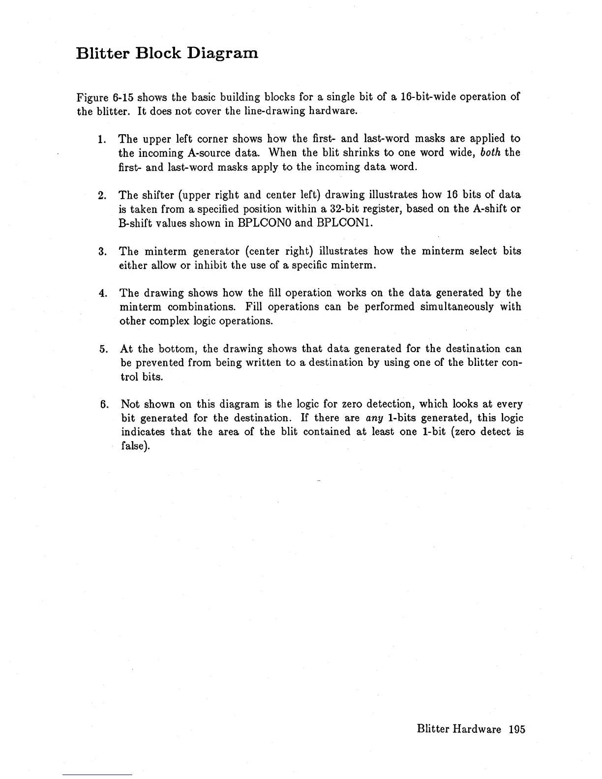
Figure 6-15 shows the basic building blocks for a single bit of a 16-bit-wide operation of
the blitter.
It
does not cover the line-drawing hardware.
1.
The
upper left corner shows how the first- and last-word masks are applied
to
the
incoming A-source data. When the blit shrinks
to
one word wide,
both
the
first- and last-word masks apply
to
the incoming
data
word.
2.
The
shifter (upper right and center left) drawing illustrates how
16
bits of
data
is
taken from a specified position within a 32-bit register, based on the A-shift or
B-shift values shown
in
BPLCONO and BPLCONl.
3.
The
minterm generator (center right) illustrates how the minterm select bits
either allow or inhibit the use of a specific minterm.
4.
The
drawing shows how the
fill
operation works on the
data
generated by the
min term combinations. Fill operations can be performed simultaneously with
other
complex logic operations.
5.
At
the bottom, the drawing shows
that
data
generated for the destination can
be
prevented from being written
to
a destination by using one of the blitter con-
trol bits.
6.
Not shown on this diagram
is
the logic for zero detection, which looks
at
every
bit
generated for the destination.
If
there are any I-bits generated, this logic
indicates
that
the area of the blit contained
at
least one I-bit (zero detect
is
false
).
Blitter Hardware 195