If
you are using the optional genlock board for video
input
from a camera, VCR,
or
laser
disk,
the
background color will be replaced by the incoming video display.
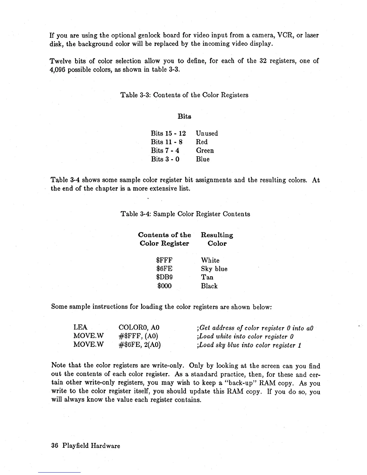
Twelve bits of color selection allow you
to
define, for each of
the
32 registers, one of
4,096 possible colors, as shown in table 3-3.
Table 3-3: Contents of
the
Color Registers
Bits
Bits
15
- 12
Bits
11
- 8
Bits 7 - 4
Bits 3 - 0
Unused
Red
Green
Blue
Table
3-4 shows some sample color register
bit
assignments and
the
resulting colors.
At
the
end
of
the chapter is a more extensive list.
Table
3-4: Sample Color Register
Contents
Contents
or
the
Color
Register
$FFF
$6FE
$DB9
$000
Resulting
Color
White
Sky blue
Tan
Black
Some sample instructions for loading the color registers are shown below;
LEA
MOVE.W
MOVE.W
COLORO,
AO
#$FFF,
(AO)
#$6FE,
2(AO)
;Get address
of
color register 0 into
aO
;Load white into color register 0
;Load
sky
blue into color register 1
Note
that
the
color registers are write-only. Only by looking
at
the screen can you find
out
the contents
of
each color register. As a
standard
practice, then, for these and cer-
tain
other
write-only registers, you may wish
to
keep a
"back-up"
RAM copy. As you
write
to
the
color register itself, you should update this RAM copy. If you do so, you
will always know
the
value each register contains.
36 Playfield Hardware