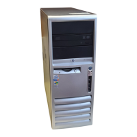
11. Pull the boards apart.
Figure 8-23 Removing the I/O board from the system board
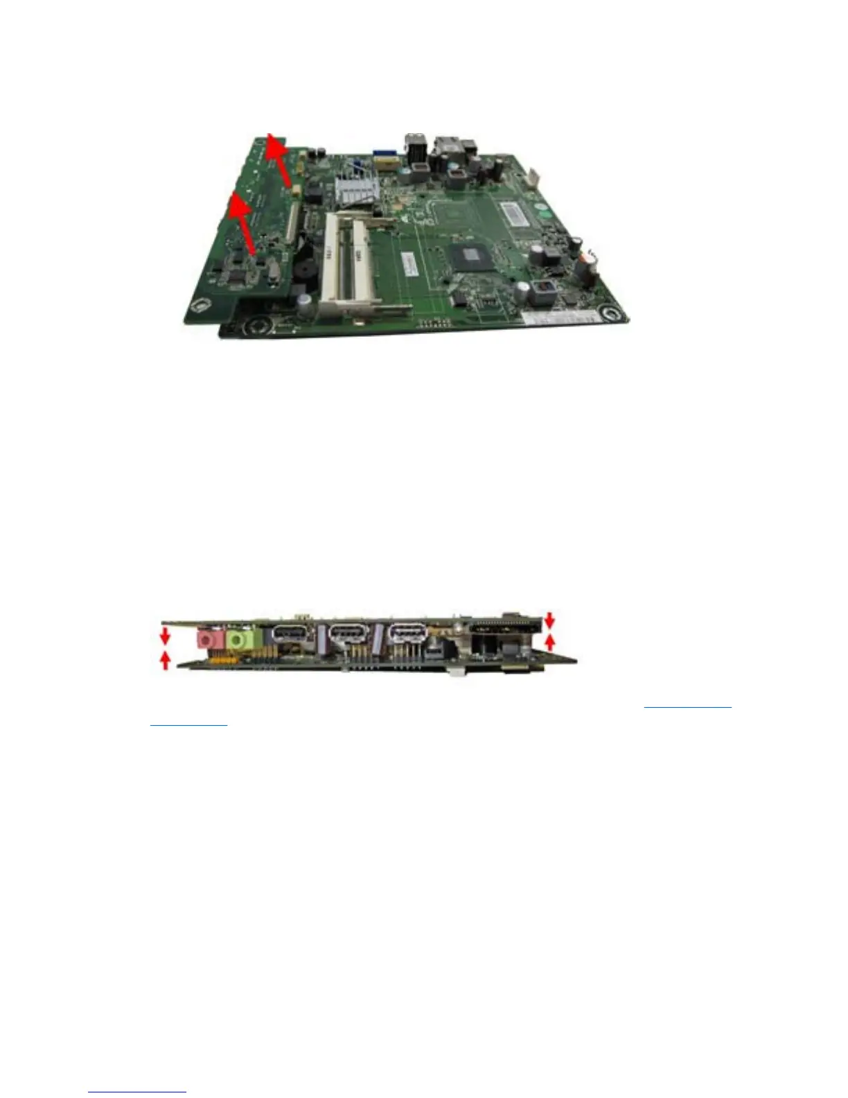
To replace the system board assembly, reverse the removal procedures.
When connecting the boards back together, connectors on the I/O board fit into the following
connectors on the system board:
●
F_AUDIO
●
P21
●
P23
●
USB1
●
USB2
Figure 8-24 Connecting the I/O board to the system board
Make sure all cables are correctly routed when reassembling the computer. See Cable Routing
on page 135 for an image that shows how to correctly route the cables.
System Board and I/O Board Assembly
129
 Loading...