14 2 Installation and Setup
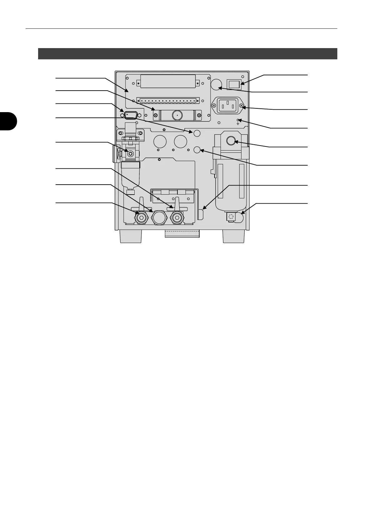
2.2 Rear Panel
A CONTROL I/O (Phoenix contact):
External device is connected to control
LS-R700 externally.
Upper: Input A Lower: Output B
B CONTROL I/O (Special specification):
D-sub connector
C COM 1:
Serial communication port.
Data is output in the designated format.
(RS-232C 9-pin male)
D G3:
Pilot pressure port for External Exhaust valve
(Push-to-connect fitting 4mm)
E PILOT PRESSURE:
Pilot pressure port
Connect clean air regulated from 400 to 700
kPa
F MASTER:
MASTER-side stop valve.
A port to connect a reference (Master).
Leave the valve opened except for
maintenance.
G EXHAUST:
Silencer for exhaust
Air is exhausted from this port after a leak test.
H WORK:
WORK-side stop valve
A port to connect a tested part (Work).
Leave the valve opened except for
maintenance.
I POWER: Power switch
J FUSE: Fuse (T2.5A 250V)
K 100 - 240 VAC~: Power inlet
L FG: Grounding
M TEST PRESSURE:
Test pressure port
(Push-to-connect fitting 4mm)
N BYPASS FILL (Option):
Pilot pressure port for fill valve for Bypass
circuit unit
O Stop Valve Monitoring Switch with a valve
cover (Option):
When the valve(s) is open, the cover won’t
close and the switch is not pressed.
This is to prevent leak testing with the stop
valves closed.
P EP REGULATOR (Option):
Electro-Pneumatic regulator connector
WORK
COSMO INSTURUMENTS CO., LTD
MADE IN JAPAN
MASTEREXHAUST
G3
T2.5A–250V
100-240VAC~50/60Hz
100VA MAX.1ph
POWER
COM1
BYPASS
FILL