Table of Contents 1
TABLE OF CONTENTS
INSTALLATION MANUAL
1
1 Introduction .................................................................................................................. 7
1 Introduction ......................................................................................................................................... 8
2 Safety Precautions ............................................................................................................................. 8
3 Notes .................................................................................................................................................... 9
2
2 Installation and Setup ................................................................................................ 11
1 Unpacking .........................................................................................................................................12
1.1 Accessories ....................................................................................................................................12
1.2 Items to Be Prepared By the Customer .........................................................................................12
2 Part Identifications ...........................................................................................................................13
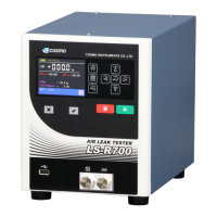
2.1 Front Panel .....................................................................................................................................13
2.2 Rear Panel ......................................................................................................................................14
2.3 Operation Keys ...............................................................................................................................15
3 Installation .........................................................................................................................................16
3.1 Environment of Leak Tester and Leak Test Stand .........................................................................16
3.2 Installation of LS-R700 with Quick Mounting Brackets ..................................................................16
3.3 Pneumatic Hookups .......................................................................................................................18
3.4 Tubing for Tested part (Work) and Master .....................................................................................20
3.5 Power Source .................................................................................................................................20
3.6 Control I/O Connector ....................................................................................................................21
4 Turning on Power for the First Time ..............................................................................................22
3
3 Interface ...................................................................................................................... 23
1 Control I/O Port .................................................................................................................................24
1.1 Standard Control I/O Port: Phoenix Contact ...............................................................................24
1.2 Control I/O Port D-SUB Connector (Special Spec.) .................................................................25
1.3 Input Specifications ........................................................................................................................26
1.4 Output Specifications ......................................................................................................................26
1.5 Typical PLC Connection .................................................................................................................28
1.6 Channel Code .................................................................................................................................29
1.7 Stage Number Output .....................................................................................................................29
1.8 Signal Timing Charts ......................................................................................................................30
1.9 Checking Wiring with I/O Monitor ...................................................................................................31
2 RS-232C Serial Interface Port .........................................................................................................32
2.1 RS-232C Interface ..........................................................................................................................32
2.2 Interface Cable Wiring Example.....................................................................................................32
2.3 Formats of RS-232C Output...........................................................................................................33
2.4 Data Format ....................................................................................................................................33
2.5 Checksum .......................................................................................................................................38
2.6 Printer .............................................................................................................................................38
3 USB Port ............................................................................................................................................40