3 Interface 31
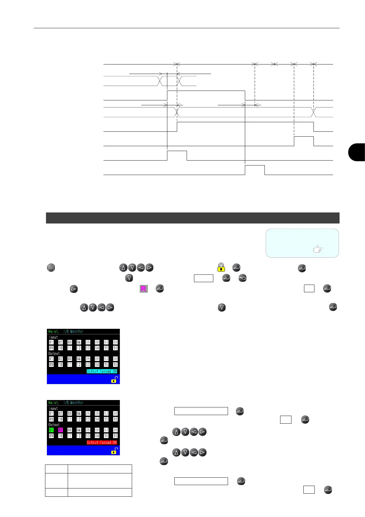
Charge Hold Timing Chart
*1 CH # is acceptable in the WAIT stage, but not in any other stage.
1.9 Checking Wiring with I/O Monitor
This can be used to check if the wire connection to external devices is correct.
First, unlock settings and switch to Manual after power is turned on.
Go to:
> Main Menu > Press to move the cursor to > > Settings Unlock >
> Enter a passcode > Press to move the cursor to Unlock > > with
> Press to move the cursor to > > “Switching to Manual Mode OK to continue?” > Yes >
Then press to move the cursor to Maint. > Press to move the cursor to I/O Monitor >
Input
The pins lit green are receiving the signals.
Output
1) Forcing output signals.
Go to: Output Forced ON >
> “Forcing Output Signal OK to continue?” > Yes >
2) Press to select the pin(s) to be checked
> > Signal(s) will be transmitted.
3) Press to selecting the pins again
> > Signals are reset.
4) Clearing Force output signals.
Go to: Output Forced ON >
> “Clearing Forced Output Signal OK to continue?” > Yes >
100
ms(MIN.)
300ms(MAX.)
300ms(MAX.)
300ms(MIN.)
WAIT
END
EXH
BLW
CHG
STAGE#
"0""1""2"or"3"
STOP (Manual)
CHG HOLD (Manual)
END
BUSY
CH# (Remote) *1
CHG HOLD (Remote)
"0"
"1"
WAIT/DL1/CHG/BAL1/DL2/BAL2/DET
Refer to
“
4
4 BASIC OPERATIONS”
for the details.
Pink Currently transmitted
while the cursor is there