CTH200 Series PLC User Manual
• Address: Set the Start address for parameters.
• Length: It’s required for Total length of configured R/W data is multiple of 4.
• Unit: Use Default value, not editable.
End: Use the value calculated by system.
Memory image: Select the Memory image type for CPU, the available type is V and Q.
Clear output when PLC STOP: Check this option to clear the contents in image address; or else
the contents remain unchanged.
Notice
For valid address range, refer to Table 6-2;
The EDS Importing for third-party slave is not supported currently, please refer to
the related product manuals for inputting main index and sub index;
In actual connection. If the third-party slave has detected error, the corresponding
SMB information area would display : 0x7 configuration parameter error;
For details of Cotrust Servo Drives, please visit at http://www.co-trust.com
4. Connection and Configuration of Hardware
Connect CPU H226XL with PC by using communication cable (the USB end connects to the
USB socket of PC, the RS485 end connects to the RS485 port of CPU H226XL).
Connect the CAN port on CAN-01 board of CPU to the CAN port of SM277C by using
communication cable.
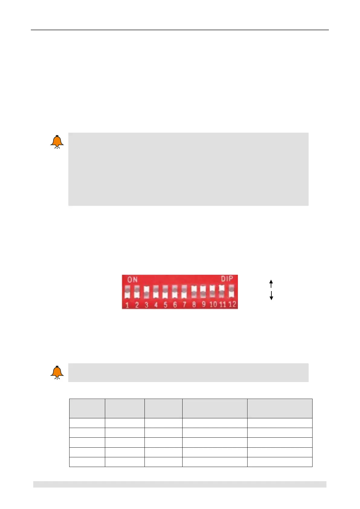
Set the DIP switch referring to the Table 6-3: Communication rate is 1000kbps, Node ID is 4.
Figure 6-3 DIP switch selection
DIP7-DIP1 (Node address): in binary, MSB - DIP7, LSB - DIP1.
DIP10-DIP8 (Baud rate): in binary, MSB - DIP10, LSB - DIP8.
0 is the global address, which is forbidden while using.
Table 6-3 DIP switch configuration
Communication rate
(kbit/s)