CTH200 Series PLC User Manual
【Example】
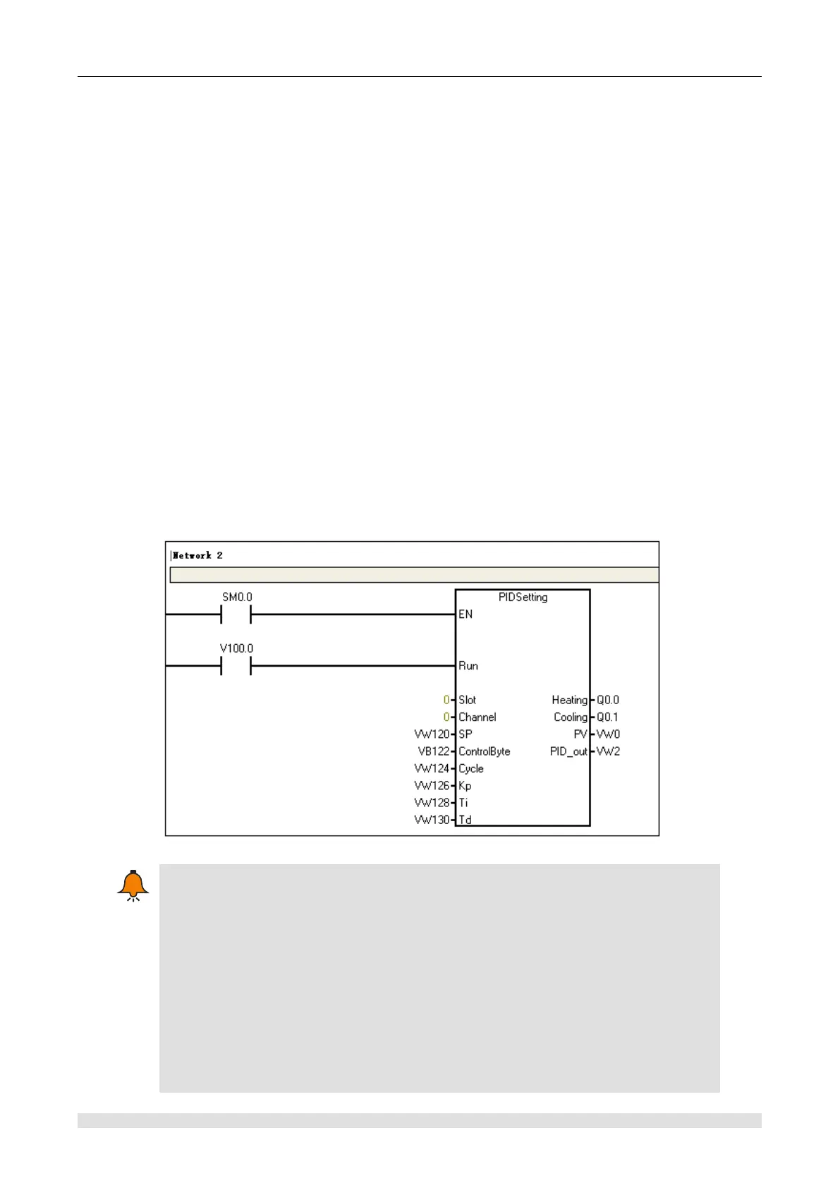
System description
This routine sets the parameters of the first PID loop (channel 0) of SM231-7TD expansion
module (slot 0). Call PIDSetting to set the loop parameters, no need to calculate the PID
parameter address, just input the slot and channel number where the loop is, and then enable
Run to run the loop.
Q0.0 is the positive pulse output; Q0.1 is negative pulse output;
VW0 is the actual temperature; VW2 is PID analog output;
Use other addresses to Modify PID setting parameters;
Set temperature: VW120;
Control Word: VB122;
Pulse output cycle: VW124;
Kp: VW126;
Ti: VW128;
Td: VW130;
Application program
Note
For PID modules normal use, please do not occupy following PID V storage when
programming.
Address that module occupied in slot 0: VW2048 to VW2298
Address that module occupied in slot 1:VW2304 to VW2554
Address that module occupied in slot 2:VW2560 to VW2810
Address that module occupied in slot 3:VW2816 to VW3066
Address that module occupied in slot 4:VW3072 to VW3322
Address that module occupied in slot 5:VW3328 to VW3578
Address that module occupied in slot 6:VW3584 to VW3834