CTH200 Series PLC User Manual
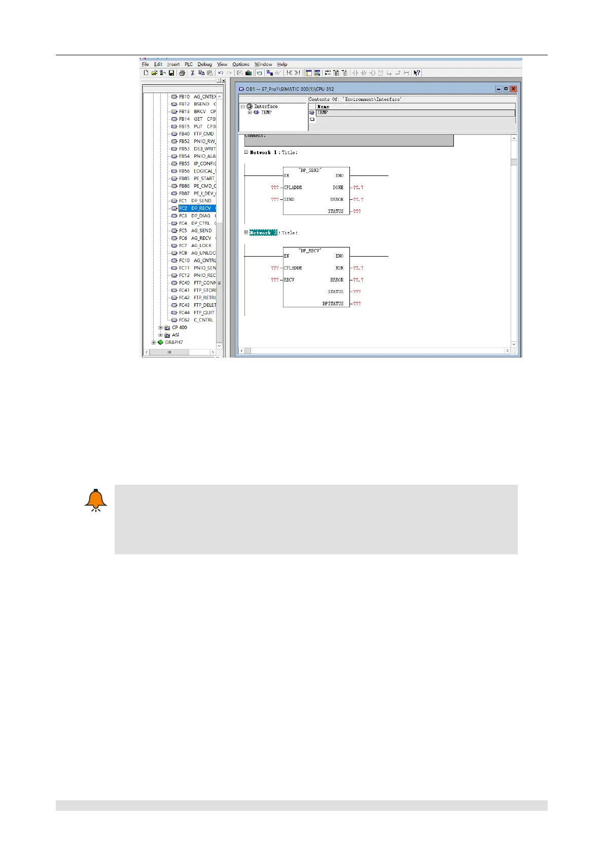
Figure H-20 Program interface
Program function description:
Execute FC1 (DP_SEND) to output CPU312 memory MB0-MB14 data to QB0-QB14 of SM277B
extension module; input SM277B extension module IB0-IB14 into the MB15-MB29 memory of
CPU312 by performing FC2 (DP_RECV).
CPLADDR: Address 256(16#100) of CP342-5
If you select the CPU with DP communication port (e.g., CPU313C-2DP), there is no
need to call FC1 and FC2 but directly access the address assigned by configuration
SM277B module (e.g., IB0-IB14, QB0-QB14).
2) Save user program
【Debugging】
Steps:
1) Connect CP 342-5 and SM277B, set SM277B address and middle resistance, and connect the
power supply of all devices in the system.
2) STEP7 connect to the main station and download the program to the CPU of the main station
system.
3) Set the main station as RUN.
4) Set and monitor the I/O data to be transmitted and the status results of program execution in
the STEP7 variable scale, observe the output status of the SM277B extension module and status
indicator light (LED)
Some faults may occur in the debugging process. Please refer to Appendix H.3.3 Diagnosis