CTH200 Series PLC User Manual
Set axis number(2 axes for
each EM253 module, axis
number range decided by
motion control modules
number)
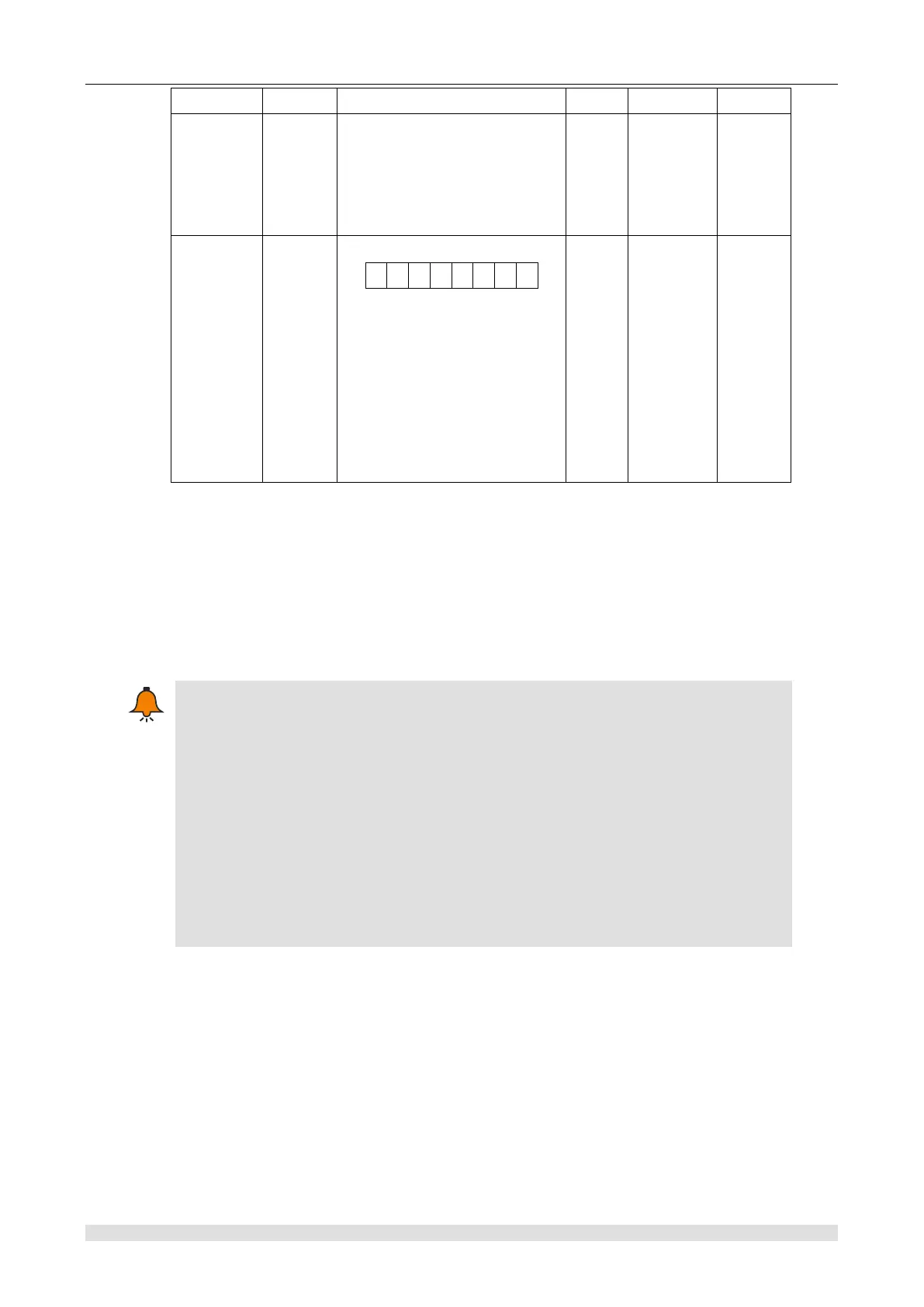
Bit0: Reset status sign bit
1—Reset complete
0—Reset uncompleted
Bit1~Bit6: reserved
Bit7: Communication status
sign bit
1—Communication timeout
0—No timeout
④ Explanation
Use 0 axis to call this instruction. After the SET rising edge enables the external reset function
and I0.2 detect the "effective reset signal", the system resets the axis 0 absolute coordinate, and
also the STATUS setting reset complete. After the RESET rising edge prohibits the external reset
function, even if I0.2 detect the "effective reset signal", the system will not reset the 0 axis
absolute coordinate, and the STATUS reset instruct is non-reset state.
The so-called "effective reset signal", the reset signal of each axis corresponding to an
external IO, and the corresponding register set its effective level. For example, 0 axis
corresponds to I0.2, and HSCO control register SM37.0 set the effective reset level of 0
axis. When set to 0, the effective reset signal of 0 axis is in I0.2 high level. When set to
1, the effective reset signal of axis 0 is in I0.2 low level; This setting is only effective if
and only if the corresponding high-speed counter (0 axis corresponds to HSC0) is
enabled, otherwise (no high-speed counter is enabled) the system default high level is
the effective reset signal. If 0 axis, I0.2 high level is the effective reset signal. In the
same way for other axes, the corresponding relation of the relevant control of each axis
is shown in ② of this section.
Set maximum acceleration instruction
① Function name: MC253_SET_MAX_ACCELE