Appendix
PTO1 free bit: 0=PTO busy, 1=PTO free
Control pulse string output and PWM of Q0.1
PTO1/PWM1 update cycle: 1=write new cycle
PWM1 update pulse width: 1=write new pulse width
PTO1 update pulse quantity: 1=write new pulse quantity
PTO1/PWM1 reference time unit: 0=1 μs/grid, 1=1 ms/grid
Synchronous update PWM1: 0=asynchronous update,
1=synchronous update
PTO1 operation: 0= single segment operation(cycle and pulse
store in SM storage), 1=multiple segment operation(envelope
table involved in V storage area)
PTO1/PWM1 mode selection: 0=PTO, 1=PWM
PTO1/PWM1 valid bit: 1=valid
PTO1/PWM1 cycle(2~65, 535 time standard)
PWM1 pulse width (0~65, 535 time standard )
PTO1 pulse count (1~232 --1)
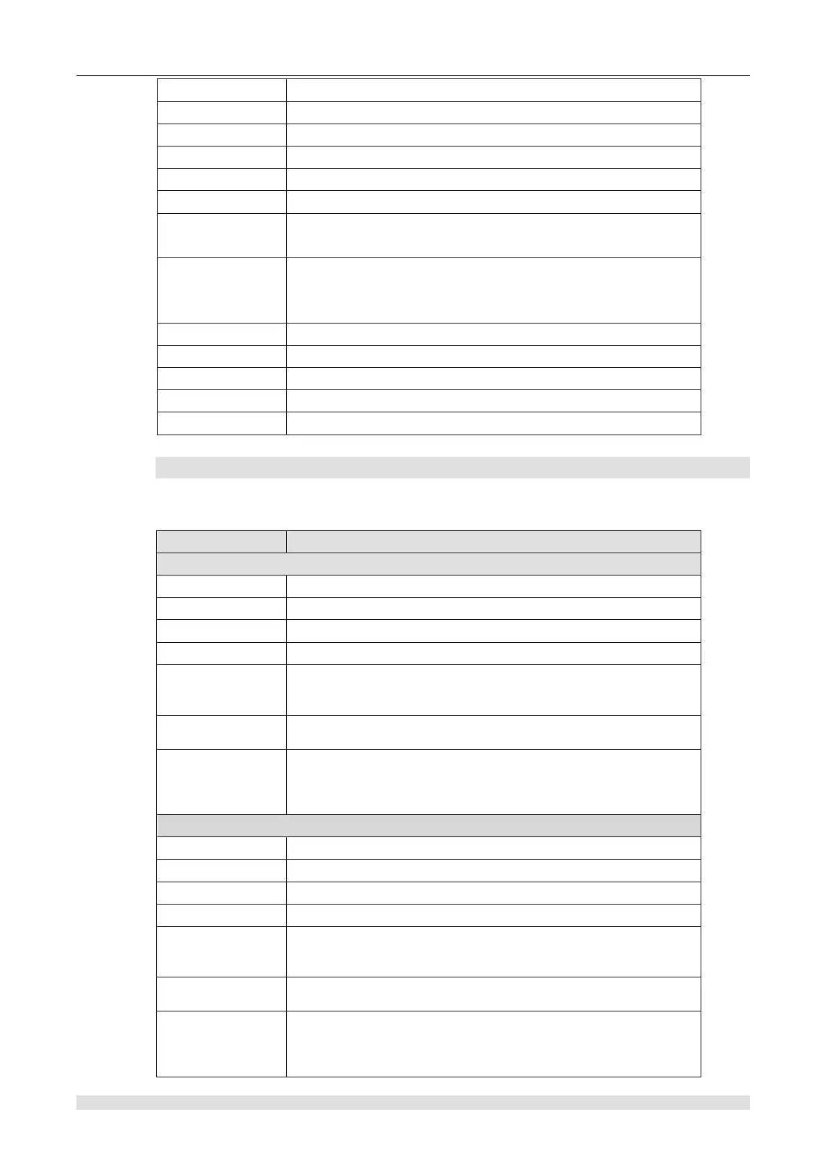
SMB86 to SMB94 and SMB186 to SMB194: receiving information control
SMB86 to SMB94 and SMB186 to SMB194 are used to control and read status about receiving
information. Detailed description is shown in the following table:
P0 receive information status byte
P0 receive information control byte
P0 start of information character
P0 end of information character
The P0 free row interval is given in ms. The first character
received at the end of free line time is the beginning of new
information.
P0 inter-character/inter-message timer timeout value
(represented by ms). If the timeout, stop receiving message.
Maximum characters P0 received(1~255 byte)
<Note> This area must set as maximum buffer you want, even if
character count information is not used to terminate it.
P1 receive information status byte
P1 receive information control byte
P1 start of information character
P1 end of information character
The P1 free row interval is given in ms. The first character
received at the end of free line time is the beginning of new
information.
P1 inter-character/inter-message timer timeout value
(represented by ms). If the timeout, stop receiving message.
Maximum characters P1 received(1~255 byte)
<Note> This area must set as maximum buffer you want, even if
character count information is not used to terminate it.