CTH200 Series PLC User Manual
Wiring diagram
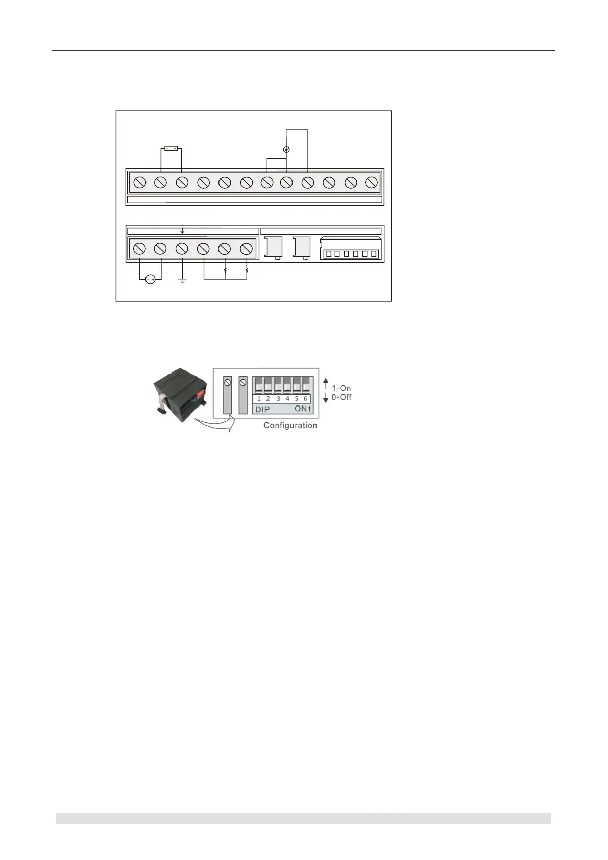
SM235 analog hybrid I/O module (CTH2 235-0KD32)
SM2 35 AI4 /AQ1 12 Bit ×
235-0KD32
A+ B + C+ D+
-
A B
-
C
-
D-
M L +
Con figur at io nGain O ffest
RA RB RC RD
M0 V 0 I 0
V Load
I Load
24VDC
Voltage input mode
Current input mode
Calibration, range and gain selection
【Calibration and DIP configuration】
【Input Calibration】
Because the calibration adjustment affects the OPAMP behind the analog multiplexer, it affects
all user input channels.In addition, because the component parameters of the input channels in
front of the multiplexer may differ, there is a slight difference of the same input signal on different
channels even after calibration.
The input has been filtered in the module, so the measurements is stable. Start the analog input
filter for all input of the module for better performance parameters. When calculating the average
value, select the sampling times above 64.
Calibration steps:
1) Cut off external power of modules, configure DIP switch to select needed range.
2) Connect CPU with module power, wait for 15min above.
3) Use a transmitter, a voltage input source or a current input source to add the zero signal to
module input.
4) Read measurement of the input in CPU.
5) Adjust OFFSET potentiometer till the reading is zero, finish zero set calibration.
6) Input a full scale signal to read the measurement in CPU.
7) Adjust GAIN potentiometer till the reading is 32000.
8) Repeat 3~7 when necessary.