CTH200 Series PLC User Manual
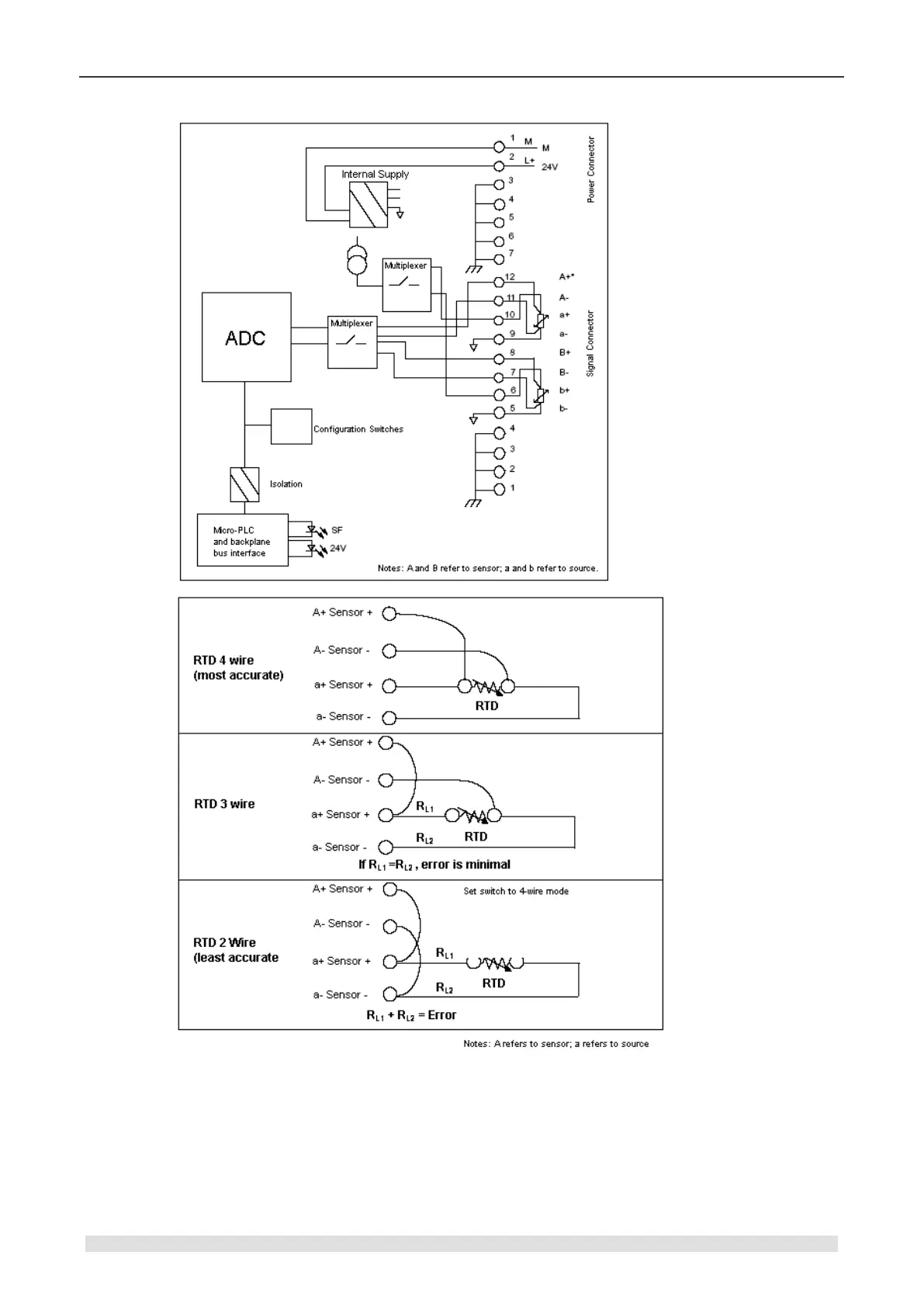
You can either directly connect the thermal resistance sensor to the SM231 module of CTH200
or use expansion wiring. The shielded wire, connect it to the ground point of PIN1-4 on signal
connector if you use, can reach the best noise resistance.
For unused channel, wire it with a resistor in place of the RTD to prevent open wire detection
from causing the SF LED to blink. The resistor must be the nominal value of the RTD.
Connect power supply to the PIN 1 and 2 of connector, and PIN 3 to its nearby shell. There are 3