Using the Monitor Ports
7-8 Operator's Manual
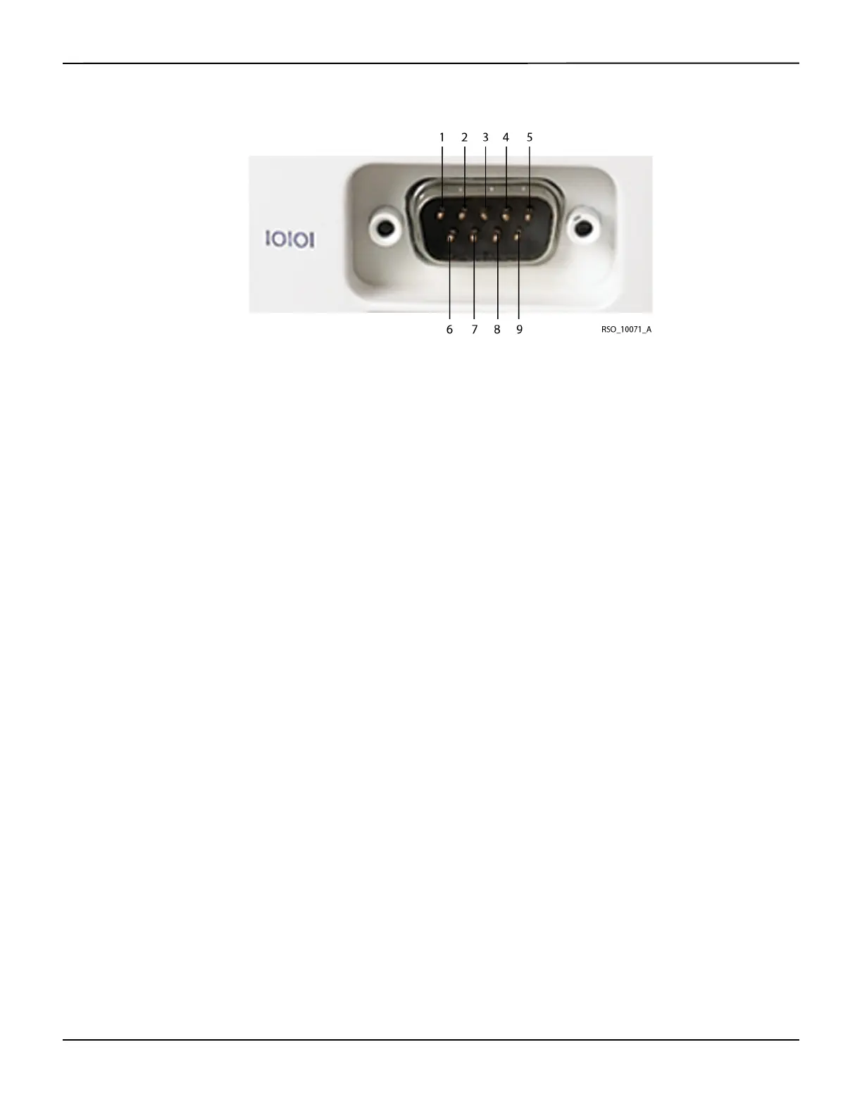
Figure7-2.Digital Output Connector Pin-Out
7.4.1
Using a Philips VueLink™* Open Interface (VOI) Module
Note:
The INVOS™ system will also interface with Hewlett Packard and Agilent multi-parameter systems that
accept the VOI B module specified in this section.
WARNING:
The VueLink™* monitor will not generate an alarm or error message if remote communication
between the VueLink™* monitor and the INVOS™ system has been broken. During this period of
no remote communication, the INVOS™ system will continue to monitor, alarm, and display status
messages. The VueLink™* monitor operator should not rely upon the distributed alarm system for
generating alarms.
In Run function, the digital output port may be set to output real-time data to communicate with
a Philips VueLink™* Open Interface (VOI) module for display on a Philips VueLink™* multi-param-
eter system. The data sent to the multi-parameter includes the rSO
2
values, alarms, and status
messages (see section 6.5 Run Function (Patient Monitoring) in Normal Mode). The multi-parameter
displays only error or alarm status messages.
The following hardware is needed for Philips VueLink™* communication:
• Philips VOI B module (Philips VueLink™* P/N M1032A #A05, driver code TU1AA)
Pin # Signal name Pin # Signal name
1 Data carrier detect 6 Data set ready
2 Receive data 7 Request to send
3 Transmit data 8 Clear to send
4 Data terminal ready 9 Ring indicator
5 Ground