4-1
4 Quick Setup
4.1 Overview
This chapter briefly describes the setup of the INVOS™ regional saturation patient monitoring
system (see also Chapter 1 Introduction, Chapter 3 Installation, and Chapter 6 Operation for com-
plete instructions).
4.2 Initial Setup
1. Plug in the INVOS™ system monitor to a power source.
Note:
The blue LED illuminates to indicate the power is connected and the battery is charging. If the blue
light is not on, turn the back panel master (mains) power switch on.
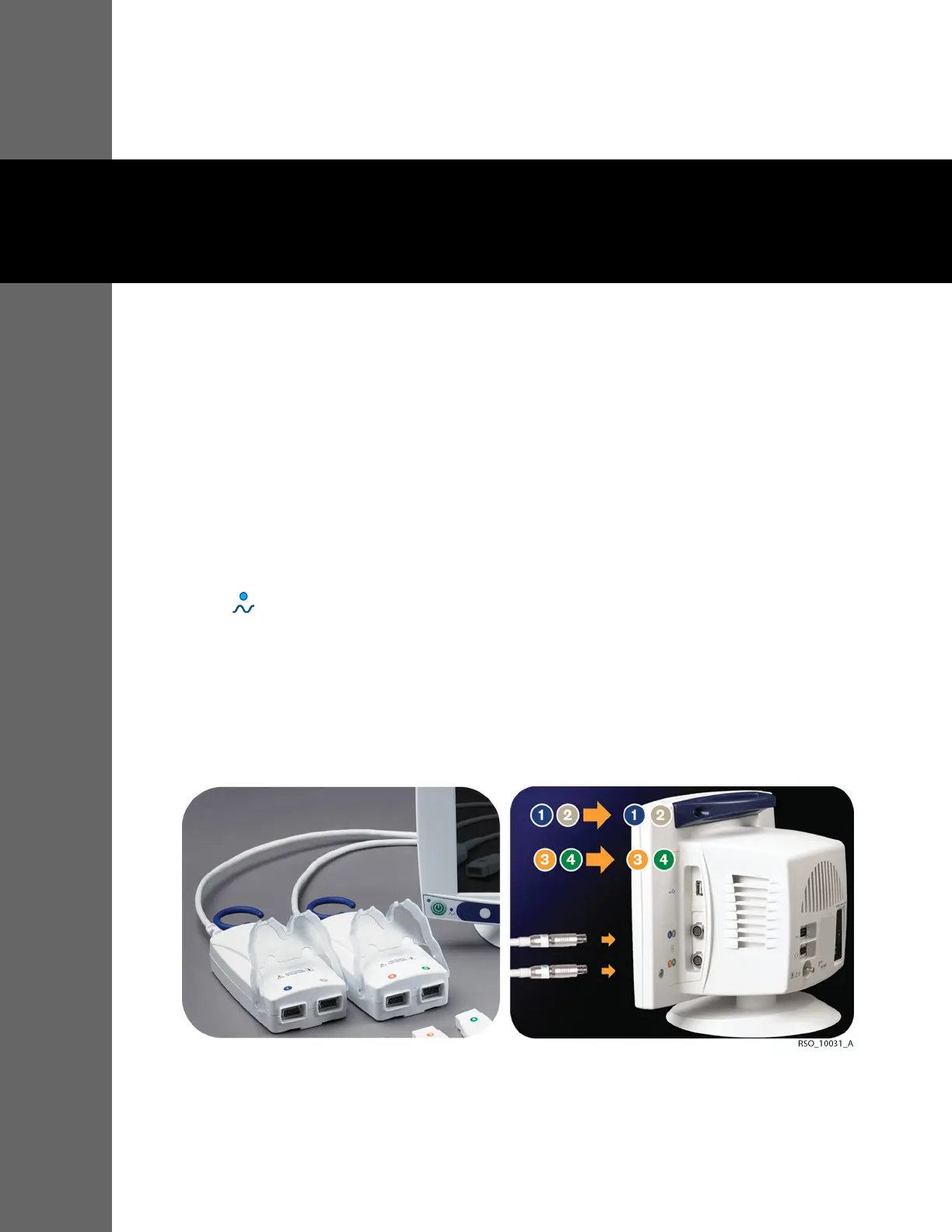
2. Connect the preamplifier or preamplifiers to the monitor. Align the red dot on the preamplifier cable
silver connector with the red dot on side panel input connection. Insert the cable connector into the
side panel connection while keeping the dots aligned. Be sure to fully insert the connector until it
locks.
Figure4-1.Connecting the Preamplifier to the Monitor
3. Connect the reusable sensor cable connectors to the preamplifier or preamplifiers. Use the color
coding.