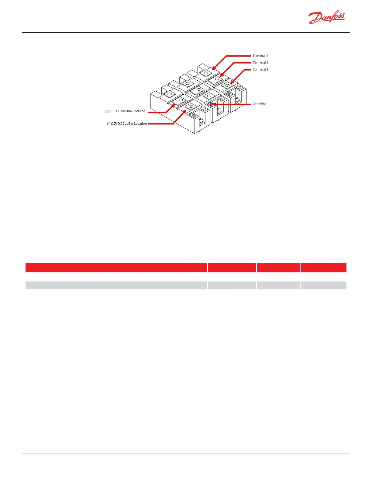
Figure 4-117 SCR DC Bus Bar to SCR Alignment
2. Installthepositivebusbarbesidethenegativebusbar(alignedwithholesidentifiedas#2onthe
diodes).
3. Thecurvedsectionofthebusbarshouldbeinstalledupwards.
4. Insertandfinger-tightenthesix(6)M6x16SCRDCBusBarfasteners.
5. Insertandfinger-tightenthetwo(2)M6x20BusBarboltsandM6nutstosecuretheSCRDCBusBarsto
theCapacitorDCBusBar.
6. Torquethesix(6)M6x16SCRDCBusBarfastenersto5Nm(44in.lb.).
7. Holdthetwo(2)M6x20BusBarboltswithawrenchandtorquetheM6nutsto10Nm(7ft.lb.).
8. Installthetopcovers.RefertoSection4.1CompressorCoversonpage52.
9. Returnthecompressortonormaloperation.
4.15.1.3 SCR DC Bus Bar Torque Specifications
Table 4-26 SCR DC Bus Bar Torque Specifications
Description Nm Ft.Lb. In.Lb.
SCRDCBusBarfastener,M6x16 5 - 44
DCCapacitorBusBartoSCRBusBarNut,M6 10 7 89
CoverFastener,M5x15 1.5 - 13
M-SV-001-EN Rev. H-1/23/2023 Page 127 of 294

 Loading...


