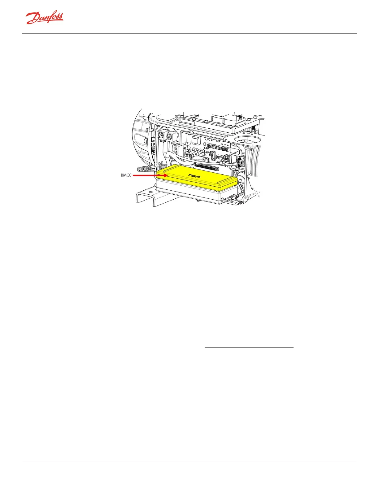
4.27 BMCC
TheBMCCisthecentralprocessorboardofthecompressor.Basedonsensorinputs,itcontrolsthebearingand
motorsystemandmaintainscompressorcontrolwithintheoperatinglimits.
l
TheBMCCuses+5VDC,+15VDC,and-15VDCpowersuppliedfromtheBackplane
l
TheBMCCrelayscompressorinformationoverRS-485/RS-232viaModbuscommunication
Figure 4-246 BMCC
4.27.1 BMCC Connections
TheBMCCisconnectedtoJ2andJ3ontheBackplane.RefertoFigure4-238BackplaneConnectionsonpage212.
4.27.2 BMCC Verification
4.27.2.1 BMCC Power Verification
1. RemovetheServiceSideCover.RefertoSection4.1.3.1ServiceSideCoverRemovalandInstallationon
page54.
2. Measurethevoltagesatthe+15V,-15V,and,+5Vtestpoints.
3. IsolatecompressorpowerandwaitfortheBackplaneLEDstogoout.
4. RemovetheBMCCfromtheBackplane.
5. TurnONtheACinputpowerandmeasurethevoltagesatthe+15V,-15V,and+5Vtestpoints.The
measuredvoltagesshouldbesimilartothosemeasuredwhentheBMCCisinstalled.
4.27.2.2 BMCC Communication Verification
ThissectionrequirestheuseoftheSMT.RefertotheServiceMonitoringToolsUserManualforguidance.
1. UsingtheSMTinstalledonyourcomputer,connecttothecompressorusingtheCompressor
ConnectionManagertooloverRS-485&RS-232.
2. Ifthesystemisabletoconnect,theBMCCisabletocommunicatewiththeuserinterface.
3. Ifthesystemisnotabletoconnect,verify:
a. TheBMCCisproperlyconnectedtotheBackplane.
b. TheI/OcableconnectionbetweentheBackplaneandtheCompressorI/OBoardisproperly
attached.
c. ThecableconnectionbetweentheCompressorI/OBoard(RS485orRS232)andtheuserinterface
(userPCorchillercontroller)isproperlyattached.
d. InspectBackplaneforindicationofdamage.
Page 220 of 294 - M-SV-001-EN Rev. H 1/23/2023

 Loading...


