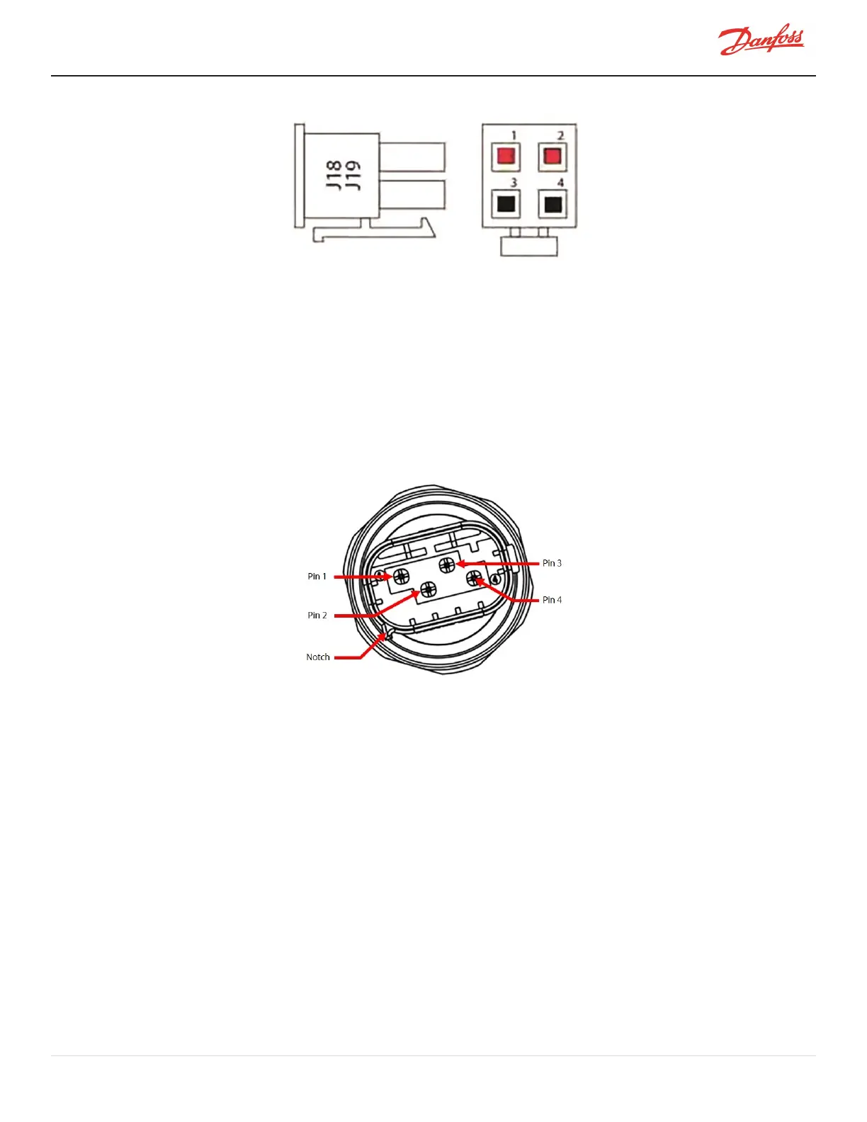
Figure 4-274 Pressure/Temperature Cable Terminals
5. Iftheintegrityofthecableisinquestion,disconnectthecompressorcontrollercablefromthe
pressure/temperaturesensorandproceedtothenextstep.
6. PlacetheleadsonTerminal1&3ofthepressure/temperaturesensor.RefertoFigure4-275
Pressure/TemperatureSensorPinLocations.
o
Thetemperaturesensorisa10KΩ@77°F(25°C)NTCthermistor.Theresistancevalueshould
correspondtoFigure4-273Temperaturevs.Resistanceonpage246
Toverifypressurereading,comparethereadoutoftheServiceMonitoringToolssoftwaretoacalibratedgauge.
DischargeandInterstagepressurereadingshouldbewithin50kPa(7.25psig).Suctionpressurereadingshouldbe
within17kPa(2.5psig).
Figure 4-275 Pressure/Temperature Sensor Pin Locations
7. Installthetopcovers.RefertoSection4.1CompressorCoversonpage52.
8. Returnthecompressortonormaloperation.
4.32.4 Pressure/Temperature Sensor Removal and Installation
4.32.4.1 Suction Pressure/Temperature Sensor Removal
1. Isolatethecompressorpower.
2. Isolatethecompressorandrecovertherefrigerantaccordingtoindustrystandards.RefertoSection3.1
RefrigerantContainmentonpage41.
3. Disconnectthesensorconnector.
4. Usingadeep15/16"socket,removethesensorfromtheIGVHousingAssembly.
M-SV-001-EN Rev. H-1/23/2023 Page 247 of 294

 Loading...


