4.26.3.2 Serial Driver Output Voltage Verification
1. RemovetheServiceSideCover.RefertoSection4.1.3.1ServiceSideCoverRemovalandInstallationon
page54.
2. IsolatecompressorpowerandwaitfortheBackplaneLEDstogoout.
3. Waitaminimumofone(1)minute.
4. Reapplycompressorpower.
l
TheAlarmLEDwillilluminategreenandtheCool-H,Cool-LandRunLEDswillilluminateamber,all
foraboutfive(5)seconds.TheAlarmLEDwillthenswitchtoredandtheotherswillturnoff.
l
Afterthecompressorcompletesstart-upcheck,theAlarmLEDwillchangetogreen(providedno
alarmispresent)andtheIGVLEDswillflickeruntiltheIGVisreset.Additionally,ifanexternal
expansionvalveisconnectedtotheI/Oboard,theLEDsontheI/Oboardwillflickerastheexternal
expansionvalveisreset.
5. InstalltheServiceSideCover.RefertoSection4.1.3.1ServiceSideCoverRemovalandInstallationon
page54.
4.26.4 Serial Driver Removal and Installation
4.26.4.1 Serial Driver Removal
1. Isolatecompressorpower.
2. RemovetheServiceSideCover.RefertoSection4.1.3.1ServiceSideCoverRemovalandInstallationon
page54.
3. WaitfortheLEDsontheBackplanetoturnoff.
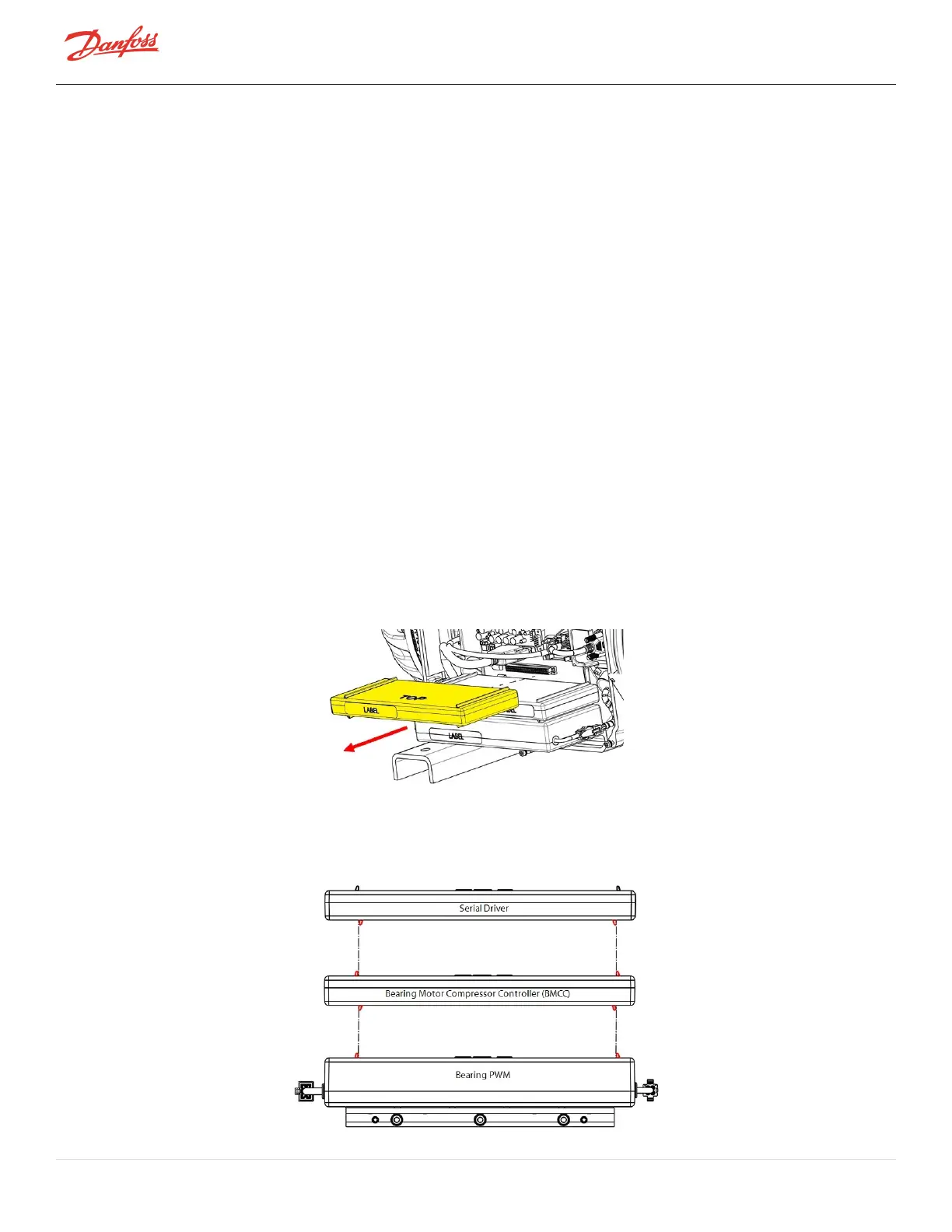
4. CarefullydisconnecttheSerialDriverfromtheBackplaneandslideitslowlyawayfromthecompressor.
RefertoFigure4-244SerialDriverRemoval.
Figure 4-244 Serial Driver Removal
4.26.4.2 Serial Driver Installation
1. CarefullyaligntheSerialDriverontopoftheBMCC.RefertoFigure4-245InsertionGuides.
Figure 4-245 Insertion Guides
Page 218 of 294 - M-SV-001-EN Rev. H 1/23/2023

 Loading...


