5. PulltheBMCCoutofitsslot.Makesureyoudonotdamagetheconnectorpins.KeeptheBMCCina
safeplace.RefertoSection4.27BMCConpage220.
6. Unplugthecableharnessfromthe4-pinfeedthroughandthe6-pinfeedthrough.
7. Removethethree(3)M5x10fastenersandpulltheBearingPWMoutofitsslot.Makesureyoudonot
damagetheconnectorpins.KeepthePWMinasafeplace.RefertoSection4.28.4PWMRemovaland
Installationonpage228.
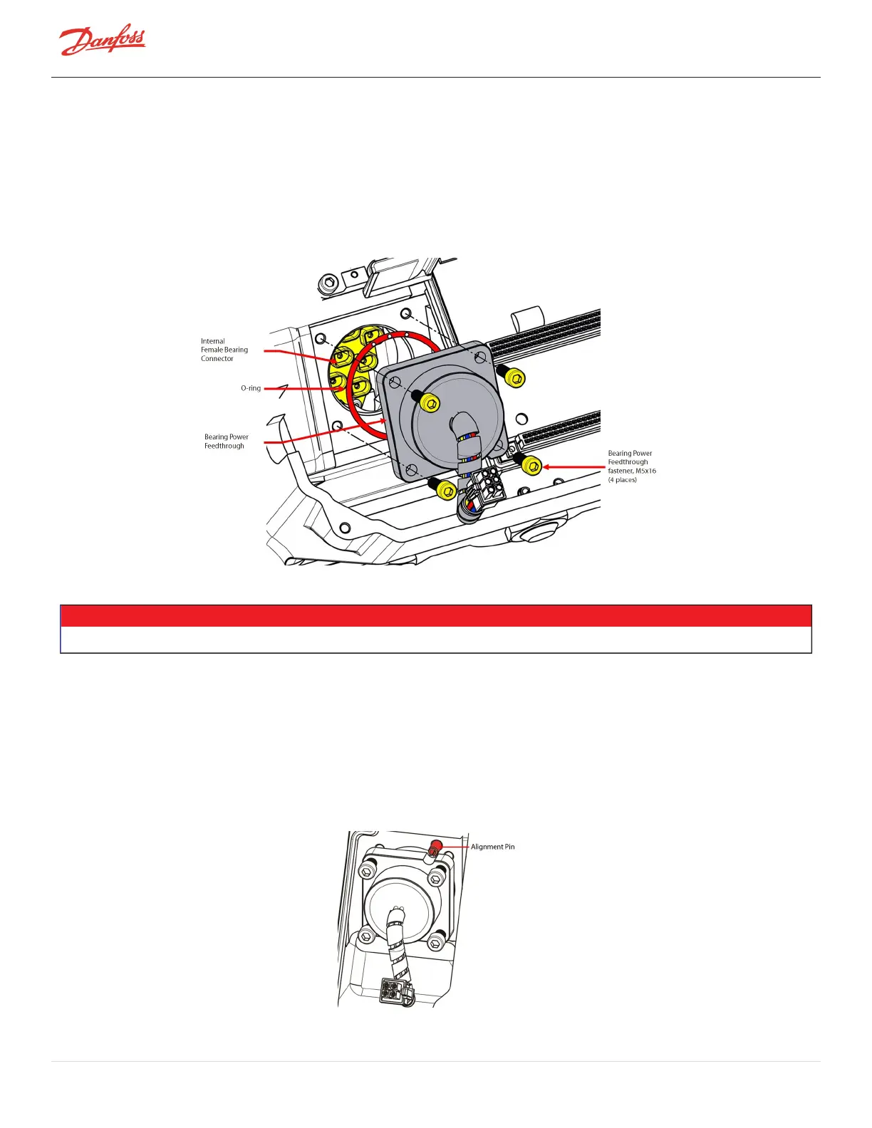
8. Removethefour(4)M5x16fastenersthatsecurethefeedthrough.
Figure 4-259 Rear Bearing Power Feedthrough Assembly
9. RemovetheFeedthrough.
NOTE
Smallplierssuchasneedle-nose,mayberequiredtoremovethefeedthrough.
4.29.4.2 Bearing Power Feedthrough Installation
1. Ifnecessary,cleanbothmatingsurfaceswithalint-freecloth.
2. ApplySuper-O-LubeonthenewO-ring.
3. InstallthelubricatedO-ringontothenewfeedthrough.
4. Installthenewfeedthroughintothecompressorhousing.Checkconnectororientationwiththe
AlignmentPinaswellastheinternalfemaleconnectorofthebearing.
Figure 4-260 Bearing Power Feedthrough Alignment Pin
Page 234 of 294 - M-SV-001-EN Rev. H 1/23/2023

 Loading...


