4.26 Serial Driver
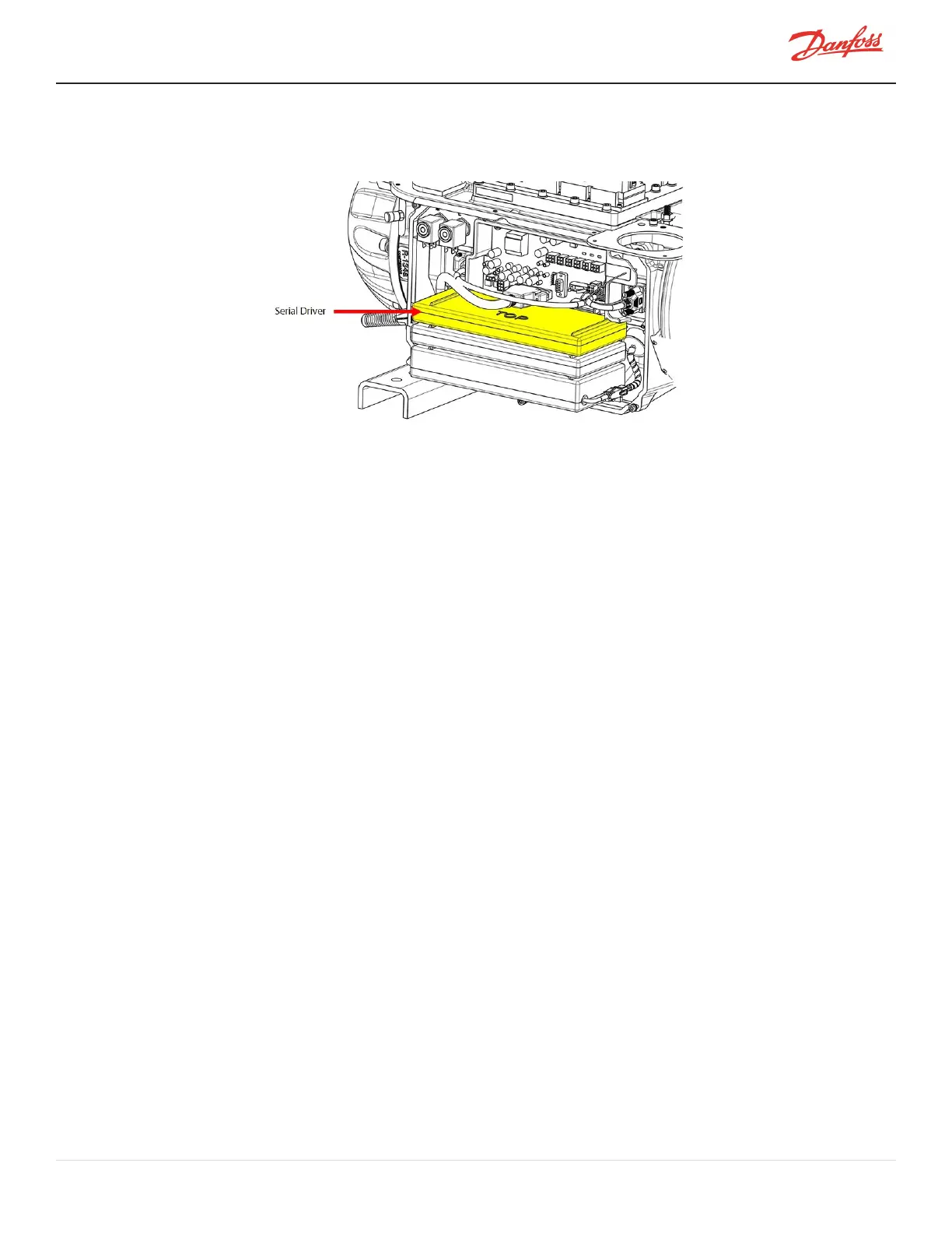
Figure 4-243 Serial Driver
4.26.1 Serial Driver Function
TheSerialDriverispoweredwith+15VDCand+24VDCfromtheBackplane.
TheSerialDriverprovides+24VDCtotheMotor-CoolingSolenoids,+15VDCtotheIGVsteppermotor,and+15VDC
totheexternalexpansionvalvesontheI/Oboard.
TheSerialDriveralsocontrolstheRUNandAlarmLEDsontheBackplaneandtheSTATUSindicatorontheI/Oboard.
AllactionsoftheSerialDriveroccurwhensignaledfromtheBMCC.
4.26.2 Serial Driver Connections
TheSerialDriverisconnectedtoJ8oftheBackplane.AllcomponentsthatcommunicatewiththeSerialDriverare
connectedtotheBackplane.RefertoFigure4-238BackplaneConnectionsonpage212.
4.26.3 Serial Driver Verification
4.26.3.1 Serial Driver Input Voltage
1. RemovetheServiceSideCover.RefertoSection4.1.3.1ServiceSideCoverRemovalandInstallationon
page54.
2. Withmainpoweron,usingamultimetersetforDCvoltagemeasurements,verifythevoltageonthe
Backplane+15Vand+24VtestpointsasdefinedinTable4-40BackplaneTestPointsonpage213for
thelocationsofthetestpoints.TheresultsshouldbewithinthevoltagerangespecifiedinTable4-42
BackplaneTestPointValuesonpage215.
3. IsolatecompressorpowerandwaitfortheBackplaneLEDstogoout.
4. UnplugconnectorsJ4andJ24fromtheBackplane.
5. Usingamultimetersetforresistancemeasurements,placethemultimeterleadsintheBackplane+15V
and+24VtestpointsasdefinedinSection4.25.2.1LEDLocationsonpage213.Theresultsshouldbe
greaterthantheresistancespecifiedinTable4-42BackplaneTestPointValuesonpage215.
6. InstalltheServiceSideCover.RefertoSection4.1.3.1ServiceSideCoverRemovalandInstallationon
page54.
7. Returnthecompressortonormaloperation.
M-SV-001-EN Rev. H-1/23/2023 Page 217 of 294

 Loading...


