thefollowingthree(3)steps.
7. Keepingthered(+)multimeterleadonthephase1ACterminal,placetheblack(-)multimeterleadon
theDC-terminal.Themeasuredvalueshouldbeopen.
8. Placetheblack(-)multimeterleadonthephase1ACterminalandthered(+)multimeterleadonthe
DC+terminalandrecordtheresults.Themeasuredvalueshouldbeopen.
9. Keepingtheblack(-)multimeterleadonthephase1ACterminal,placethered(+)multimeterleadon
theDC-terminal.Themeasuredvalueshouldbe0.275V–0.4V.
10. RepeatSteps6through9fortheremainingInverterphases.
NOTE
Thesevaluescanvarydependingonthemeterbeingused.Themainideaisthatthevaluesbeconsistentbetweenphases.
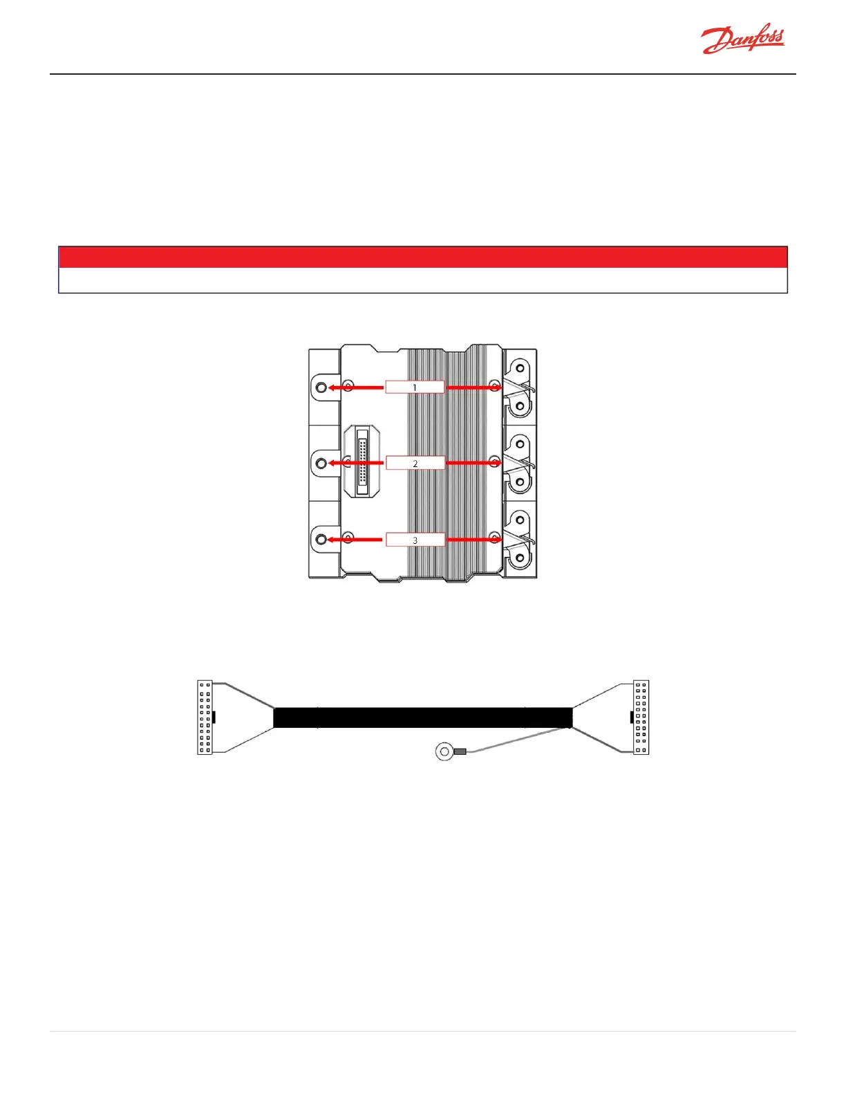
Figure 4-190 Inverter Diode Measurements (Skiip 613 Shown)
4.22.3 Inverter Cable Harness
Figure 4-191 Inverter Cable Harness
4.22.4 Inverter Cable Harness Removal and Installation
4.22.4.1 Inverter Cable Harness Removal
1. IsolatethecompressorpowerasdescribedinSection1.8ElectricalIsolationonpage22.
2. RemovetheServiceSideCover.RefertoSection4.1.3.1ServiceSideCoverRemovalandInstallationon
page54.
3. RemovetheSoftStart.RefertoSection4.14.3SoftStartRemovalandInstallationonpage117.
4. Usetwo(2)fingerstosimultaneouslypushoutwardontheInverterCableHarnesslatches.Referto
Figure4-192HarnessRemovalfromInverteronpage178.
M-SV-001-EN Rev. H-1/23/2023 Page 177 of 294

 Loading...


