3. InstallthewiresontheinnerthermistorterminalswhileholdingtheCoverPlate.RefertoFigure4-223
ThermistorConnectorRemovalonpage199.
NOTE
Polarityofthethermistorwiresisnotrequired.
• • • CAUTION • • •
Caremustbetakenwhileplugginginthethermistorsensorconnectors.EnsurenodamageoccurstothemountedO-ringduringthis
action.TheO-ringmustbereplacedifanydamageoccurs.
4. LowertheCoverPlateontotheMainhousing.
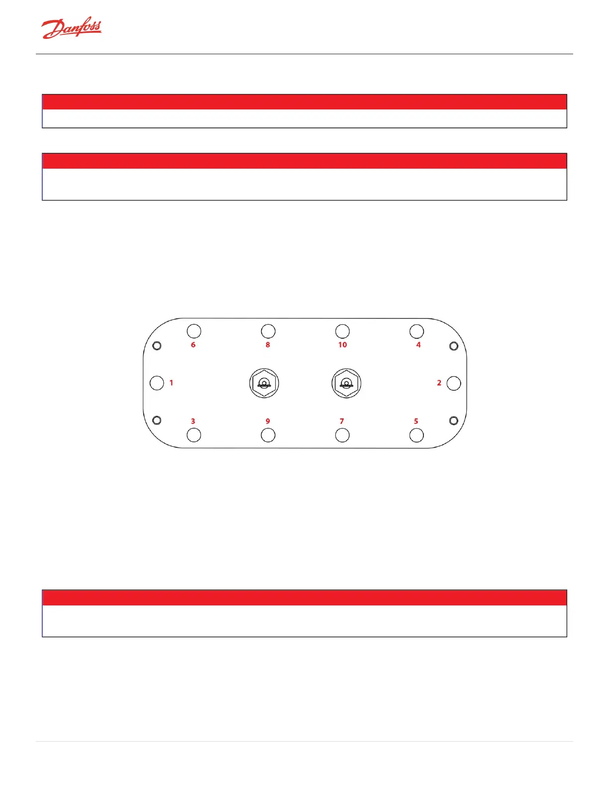
5. Usingthe10M8x25fasteners,installtheCoverPlate.Finger-tightenandthen,accordingtoFigure4-
224CoverPlateTorqueSequence,tighteninacrisscrosspatternintwo(2)stages.
l
Stage1:Tightento10Nm(7ft.lb.)
l
Stage2:Tightentoafinaltorqueof18Nm(13ft.lb.)
Figure 4-224 Cover Plate Torque Sequence
6. Leaktestandevacuateinaccordancewithstandardindustrypractices.
7. Connectthetwo(2)connectorstothethermistorsensorfeedthrough.
8. InstalltheMotorBusBars.RefertoSection4.23.5.2MotorBusBarInstallationonpage197.
9. InstalltheSoftStart.RefertoSection4.14.3SoftStartRemovalandInstallationonpage117.
10. Installthetopcovers.RefertoSection4.1CompressorCoversonpage52.
11. Returnthecompressortonormaloperation.
4.23.5.7 High Power Feedthrough Removal
• • • CAUTION • • •
Useextremecarenottodropanypartsortoolsintothemotorcavitywhenremovingthehighpowerfeedthroughs.Doingsocouldresult
incompressordamageorfailure.
1. IsolatecompressorpowerasdescribedinSection1.8ElectricalIsolationonpage22.
2. Recovertherefrigerantfromthecompressoraccordingtoindustrystandards.RefertoSection3.1
RefrigerantContainmentonpage41.
3. RemovetheSoftStart.RefertoSection4.14.3SoftStartRemovalandInstallationonpage117.
Page 200 of 294 - M-SV-001-EN Rev. H 1/23/2023

 Loading...


