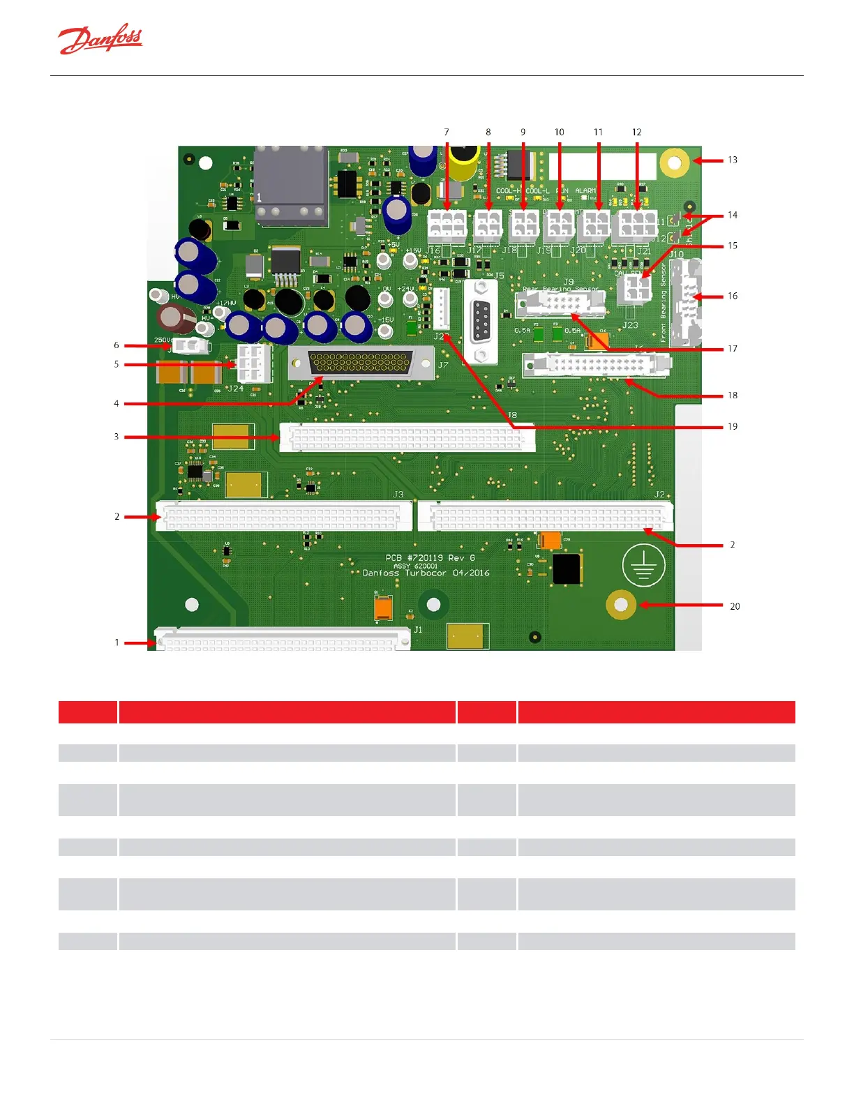
Figure 4-238 Backplane Connections
Table 4-39 Backplane Connections
No. Component No. Component
1 J1:PWMConnectionPort 11 J20:Motor-WindingSensorPort
2 J2andJ3:BMCCConnectionPort 12 J21:IGVMotorControlPort
3 J8:SerialDriverConnectionPort 13 InverterGroundScrew
4 J7:I/OCableConnection 14 J11andJ12:RearBearingSensorCabletoGround
(eithermaybeused)
5 J24:Inputof+24VDCfromDC-DC 15 J23:CavityTemperatureSensorInput
6 J4:Inputof+250VDCFromDC-DC 16 J10:FrontBearingSensorInput
7 J16:Motor-CoolingSolenoidsControlPort 17 J9:RearBearingSensorInput
8 J17:SCRTemperature(TTH/TGHInterstageTemperature/Pressure
Sensor)SensorPort
18 J6:InverterConnectionPort
9 J18:SuctionTemperature/PressureSensorPort 19 J22:SoftStartTemperatureSensor
10 J19:DischargeTemperature/PressureSensorPort 20 BackplaneGroundScrew
Page 212 of 294 - M-SV-001-EN Rev. H 1/23/2023

 Loading...


