AGC Designer’s Reference Handbook
DEIF A/S Page 136 of 168
Phase controller
When the static synchronisation is used and the synchronising is activated, the frequency controller
will bring the gen-set frequency towards the busbar frequency. When the gen-set frequency is
within 50mHz of the busbar frequency, then the phase controller takes over. This controller uses
the angle difference between the generator system and the busbar system as the controlling
parameter.
This is illustrated in the example above where the phase controller brings the phase angle from 30
deg. to 0 deg.
Close signal
The close signal will be issued when phase L1 of the synchronising generator is close to the 12
o’clock position compared to the busbar which is also in 12 o’clock position. It is not relevant to
use the response time of the circuit breaker when using static synchronisation, because the slip
frequency is either very small or non-existing.
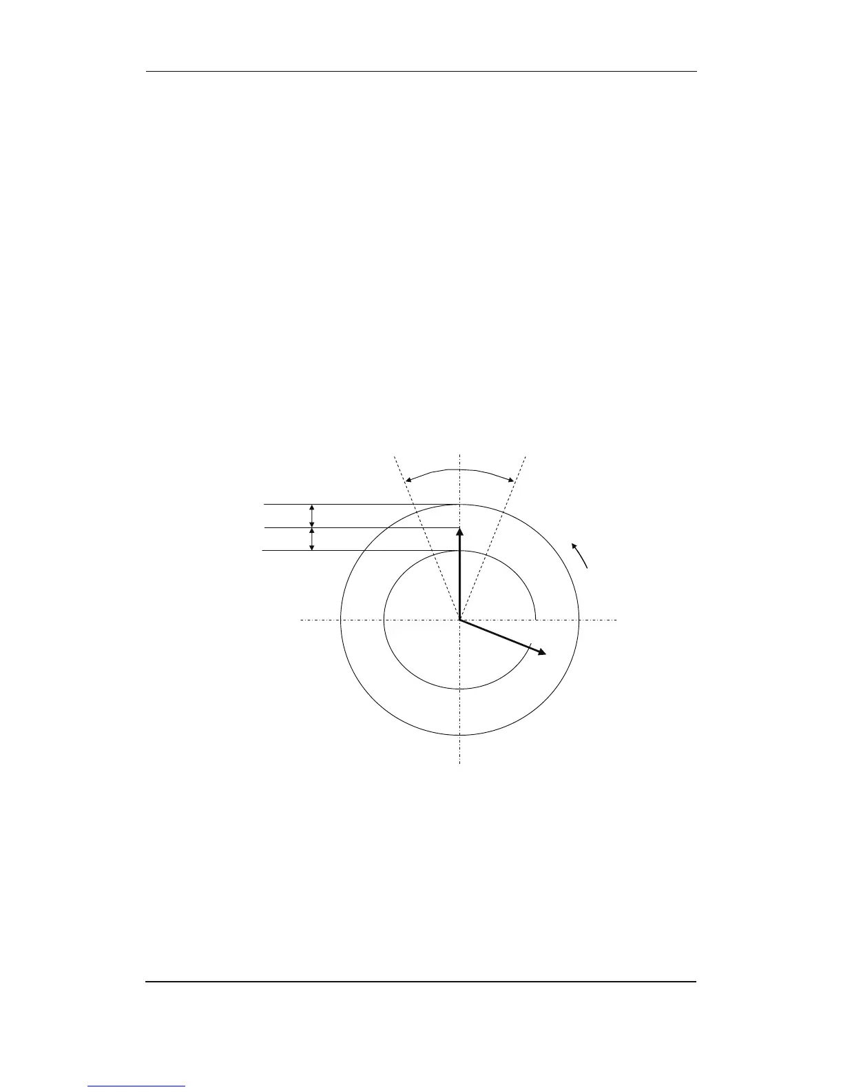
To be able to get a faster synchronisation a ‘close window’ can be adjusted. The close signal
can be issued when the phase angle U
GENL1
-U
BBL1
is within the adjusted setpoint. The range is
+/-0.1-20.0 deg. This is illustrated in the drawing below.
The synchronisation pulse is sent dependent on the settings in
2020 Dynamic synchronisation
. Depends if it is the GB or the MB, which is to be synchronised.
Load picture after synchronisation
The synchronised gen-set will not be exposed to an immediate load after the breaker closure, if
the maximum df setting is adjusted to a low value. Since the fuel rack position almost exactly
equals what is required to run at the busbar frequency, no load jump will occur.
If the maximum df setting is adjusted to a high value, then the observations in the section about
‘dynamic synchronisation’ must be observed.
Max. dU difference
Max. dU difference
Direction of
r