AGC Designer’s Reference Handbook
DEIF A/S Page 142 of 168
The breaker sequence adjustments are the following:
Menu Description Comment
2121 Breaker selection Select breakers to close: GB or
GB + TB.
2122 Timer The timer defines the period
from the excitation is started
and until the regulation is
activated. The alarms set to
'RUN' will be activated after
this timer has expired.
2123 Excitation start level The setting defines at what
level of RPM the excitation is
started.
'Close before excitation' failure
If the starting of the gen-set does not succeed, then the alarm menu 2130 ‘Excit failure’ will
occur, and the selected fail class will be executed.
Separate synchronising relay
When the AGC gives the synchronising command, then the relays on terminal 17/18/19
(generator breaker) and terminal 11/12/13 (mains breaker) will activate, and the breaker must
close when this relay output is activated.
This default function can be modified using a digital input and extra relay outputs depending on
the required function. The relay selection is made in the menu 2100, and the input is selected in
the input settings in the utility software.
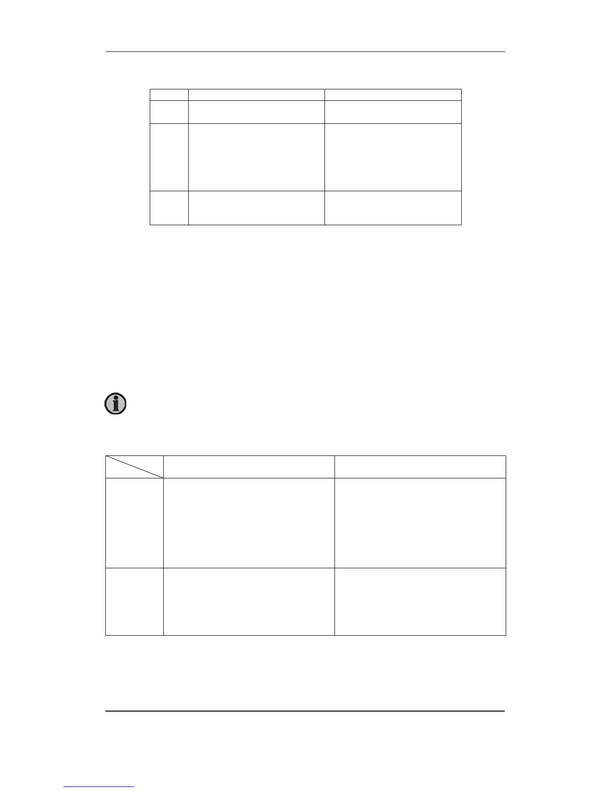
The table below describes the possibilities.
Relay
Input
Relay selected
Two relays used
Relay not selected
One relay used
Not used
Synchronising:
The breaker ON relay and the sync.
relay activate at the same time when
synchronising is OK.
Blackout closing:
The breaker ON relay and the sync.
relay activate at the same time when
the voltage and frequency are OK.
Synchronising:
The breaker ON relay activates when
synchronising is OK.
Blackout closing:
The breaker ON relay activates when
the voltage and frequency are OK.
DEFAULT selection
Low
Synchronising:
Not possible.
Blackout closing:
The breaker ON relay and the sync.
relay activate at the same time when
the voltage and frequency are OK.
Synchronising:
Not possible.
Blackout closing:
The breaker ON relay activates when
the voltage and frequency are OK.
This function is option dependent. Option M14 or M12 is required. Option M14
includes relays 1-4 and option M12 includes 13 digital inputs and relays 5-8.