AGC Designer’s Reference Handbook
DEIF A/S Page 96 of 168
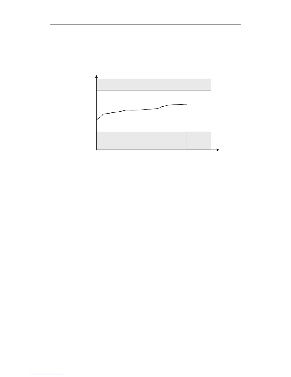
Principle
The illustration below shows that when the wire of the input breaks, the measured value will drop
to zero. Then the alarm will occur.
PT100 settings
The alarm setpoint of the PT100 inputs can be calculated in percent like this:
Example:
Required setpoint is 200 °C. The adjustment must be:
VDO settings
The alarm setpoint of the VDO inputs can be calculated in percent like this:
VDO 104, oil pressure:
VDO 105, cooling temp.:
VDO 106, fuel level:
The deviation is the alarm value entered in percent, and the setting is the required alarm setting
in ohms.
Example:
Required setpoint of VDO104 is 180Ω. The adjustment must be:
Wire failure
Wire failure
Wire break
Lower failure
limit
Upper failure
limit
Input signal
(mA, °C, b, %)
t
9,2/)40(% += tdeviation
100*240/% settingdeviation =
%83
9,2/)40200(
%
%
=
+=
deviation
deviation
%75
100*240/180
%
%
=
=
deviation
deviation
100*530/
% settingdeviation =
100*240/
% settingdeviation =