EasyManuals Logo

Dell Networking N4000 Series User Manual

Dell Networking N4000 Series
1460 pages
To Next Page IconTo Next Page
To Previous Page IconTo Previous Page
Page #1185 background imageLoading...
Page #1185 background image
Configuring OSPF and OSPFv3 1185
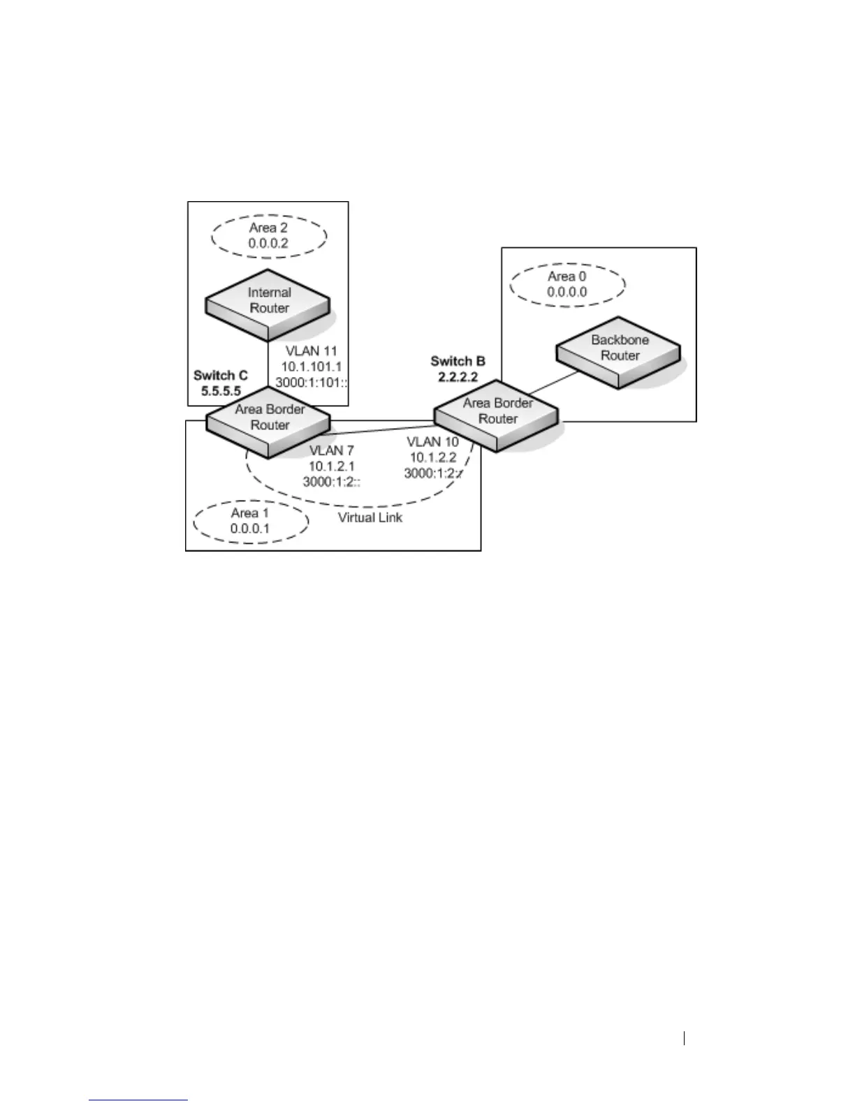
Figure 35-37. OSPF Configuration—Virtual Link
Switch B is an ABR that directly connects Area 0 to Area 1. Note that in the
previous example, Switch B connected to a stub area and an NSSA. Virtual
links cannot be created across stub areas or NSSAs.
The following commands define a virtual link that traverses Area 1 to Switch
C (5.5.5.5).
To configure Switch B:
1
Configure the virtual link to Switch C for IPv4.
console#configure
console(config)#router ospf
console(config-router)#area 0.0.0.1 virtual-link 5.5.5.5
console(config-router)#exit
2
Configure the virtual link to Switch C for IPv6.
console#configure
console(config)#ipv6 router ospf
console(config-rtr)#area 0.0.0.1 virtual-link 5.5.5.5
console(config-rtr)#exit

Table of Contents

Other manuals for Dell Networking N4000 Series

Questions and Answers:

Question and Answer IconNeed help?

Do you have a question about the Dell Networking N4000 Series and is the answer not in the manual?

Dell Networking N4000 Series Specifications

General IconGeneral
LayerLayer 3
Switching CapacityUp to 1.28 Tbps
Operating Temperature0°C to 45°C (32°F to 113°F)
Storage Temperature-40°C to 70°C (-40°F to 158°F)
SeriesN4000 Series
StackingUp to 12 units
Power SupplyDual, hot-swappable
ManagementWeb, CLI, SNMP
Humidity10% to 90% (non-condensing)

Related product manuals