Configuring Link Aggregation 935
Definitions
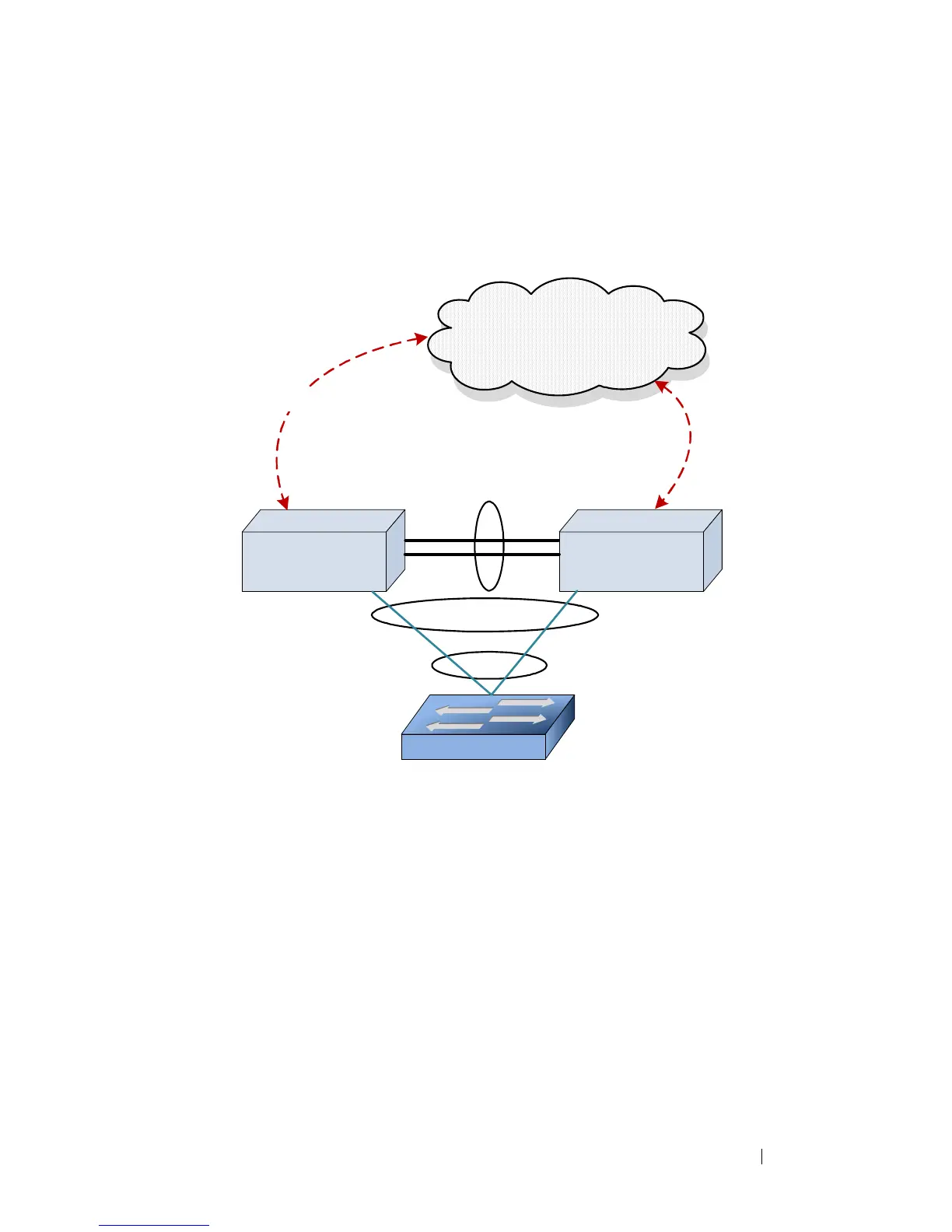
Refer to Figure 28-10 for the definitions that follow.
Figure 28-10. MLAG Components
MLAG switches: MLAG aware switches running Dell Networking OS switch
firmware. No more than two MLAG aware switches can pair to form one end
of the LAG. Stacked switches do not support MLAGs. In the above figure,
SW1 and SW2 are MLAG peer switches. These two switches form a single
logical end point for the MLAG from the perspective of switch A.
MLAG interfaces: MLAG functionality is a property of port-channels. Port-
channels configured as MLAGs are called MLAG interfaces. Administrators
can configure multiple instances of MLAG interfaces on the peer MLAG
switches. Port-channel limitations and capabilities like min-links and
maximum number of ports supported per LAG also apply to MLAG
interfaces.
SW2SW1
L3 Network
Peer-Link
A
P1
P2
P3
S2
S3
S4
P4
Virtual Link
MLAG
LAG
S1
 Loading...