106 Hardware Overview
Port and System LEDs
The front panel contains light emitting diodes (LEDs) that indicate the
status of port links, power supplies, fans, stacking, and the overall system
status.
For information about the status that the LEDs indicate, see the
User’s
Configuration Guide.
Stack Master LED and Stack Number Display
When a switch within a stack is the master unit, the stack master LED, which
is labeled M, is solid green. If the M LED is off, the stack member is not the
master unit. The Stack No. panel displays the unit number for the stack
member. If a switch is not part of a stack (in other words, it is a stack of one
switch), the M LED is illuminated, and the unit number is displayed.
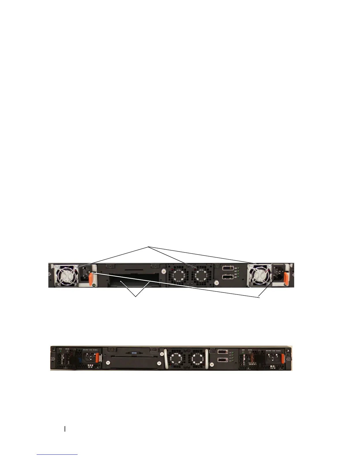
N3000 Series Back Panel
The following images show the back panels of the N3000 switches.
Figure 3-11. N3000 Back Panel
Figure 3-12. N3024P/N3048P Back Panel
Dual 10G Slots for SFP+ or
10GBASE-T Modules
AC Power
Receptacle
Fan Vents
 Loading...