EasyManuals Logo

Dell Networking N4000 Series User Manual

Dell Networking N4000 Series
1460 pages
To Next Page IconTo Next Page
To Previous Page IconTo Previous Page
Page #752 background imageLoading...
Page #752 background image
752 Configuring the Spanning Tree Protocol
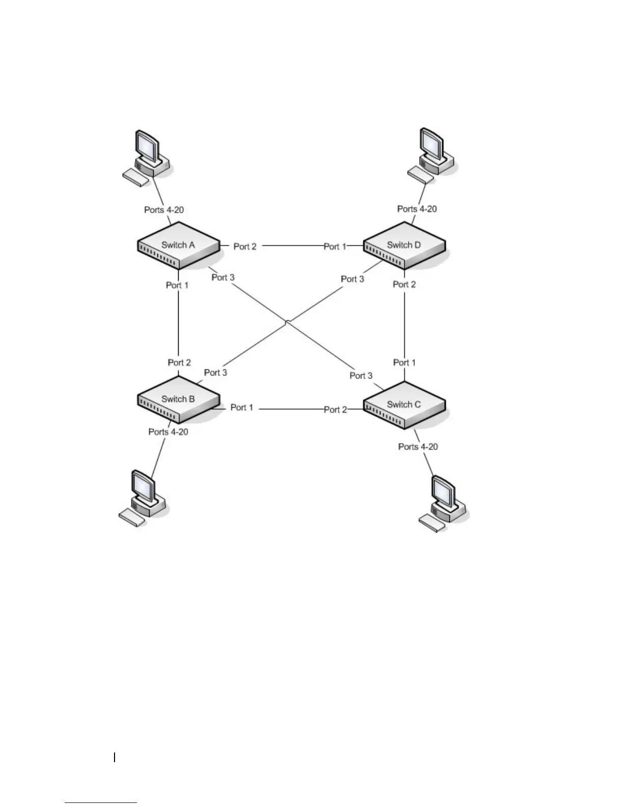
Figure 22-19. STP Example Network Diagram
Of the four switches in Figure 22-19, the administrator decides that Switch A
is the most centrally located in the network and is the least likely to be moved
or redeployed. For these reasons, the administrator selects it as the root bridge
for the spanning tree. The administrator configures Switch A with the highest
priority and uses the default priority values for Switch B, Switch C, and
Switch D.
For all switches, the administrator also configures ports 4–17 in Port Fast
mode because these ports are connected to hosts and can transition directly
to the Forwarding state to speed up the connection time between the hosts
and the network.

Table of Contents

Other manuals for Dell Networking N4000 Series

Questions and Answers:

Question and Answer IconNeed help?

Do you have a question about the Dell Networking N4000 Series and is the answer not in the manual?

Dell Networking N4000 Series Specifications

General IconGeneral
LayerLayer 3
Switching CapacityUp to 1.28 Tbps
Operating Temperature0°C to 45°C (32°F to 113°F)
Storage Temperature-40°C to 70°C (-40°F to 158°F)
SeriesN4000 Series
StackingUp to 12 units
Power SupplyDual, hot-swappable
ManagementWeb, CLI, SNMP
Humidity10% to 90% (non-condensing)

Related product manuals