IS area address, system ID, and N-selector. The last byte is the N-selector. All routers within an area have
the same area portion. Level 1 routers route based on the system address portion of the address, while
the Level 2 routers route based on the area address.
The NET length is variable, with a maximum of 20 bytes and a minimum of 8 bytes. It is composed of the
following:
• area address — within your routing domain or area, each area must have a unique area value. The first
byte is called the authority and format indicator (AFI).
• system address — the router’s MAC address.
• N-selector — this is always 0.
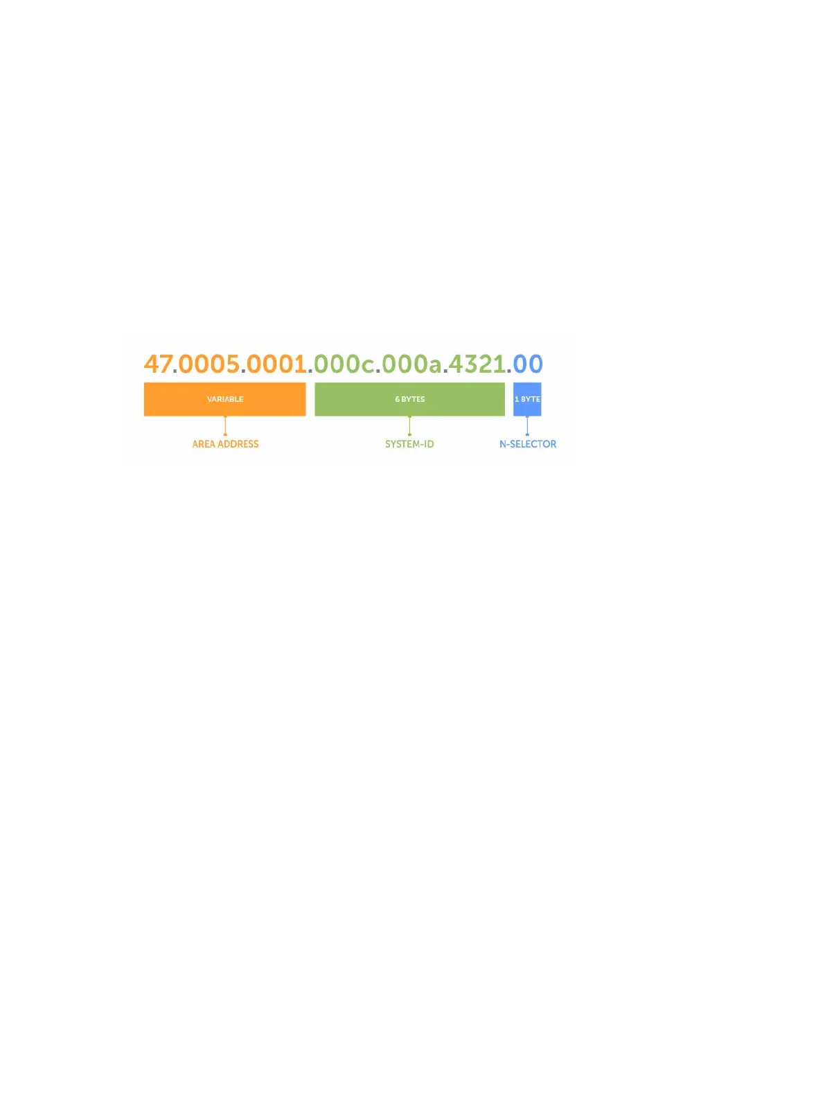
The following illustration is an example of the ISO-style address to show the address format IS-IS uses. In
this example, the first five bytes (47.0005.0001) are the area address. The system portion is 000c.000a.
4321 and the last byte is always 0.
Figure 56. ISO Address Format
Multi-Topology IS-IS
Multi-topology IS-IS (MT IS-IS) allows you to create multiple IS-IS topologies on a single router with
separate databases. Use this feature to place a virtual physical topology into logical routing domains,
which can each support different routing and security policies.
All routers on a LAN or point-to-point must have at least one common supported topology when
operating in Multi-Topology IS-IS mode. If IPv4 is the common supported topology between those two
routers, adjacency can be formed. All topologies must share the same set of L1-L2 boundaries.
You must implement a wide metric-style globally on the autonomous system (AS) to run multi-topology
IS-IS for IPv6 because the Type, Length, Value (TLVs) used to advertise IPv6 information in link-state
packets (LSPs) are defined to use only extended metrics.
The multi-topology ID is shown in the first octet of the IS-IS packet. Certain MT topologies are assigned
to serve predetermined purposes:
• MT ID #0: Equivalent to the “standard” topology.
• MT ID #1: Reserved for IPv4 in-band management purposes.
• MT ID #2: Reserved for IPv6 routing topology.
• MT ID #3: Reserved for IPv4 multicast routing topology.
• MT ID #4: Reserved for IPv6 multicast routing topology.
• MT ID #5: Reserved for IPv6 in-band management purposes.
534
Intermediate System to Intermediate System