2-9
2
Introduction
2.5.4 Function Keys
There are no symbols on the function keys. The functions of keys depend on symbols ap-
pearing on the LCD. Please see the table below.
No. Symbol Function
1
Goes back to previous screen or cancels current selection.
2
Moves up.
3
Moves down.
4
Moves left.
5
Moves right.
6
Increases number.
7
Decreases number.
8
&RQ¿UPVVHOHFWLRQRUJRHVWR0DLQ0HQX
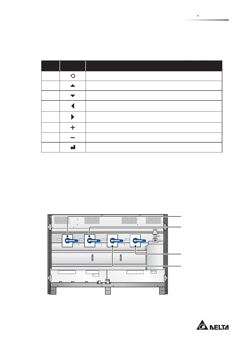
2.6 Internal Mechanisms
2.6.1 Input & Output Switches
The input and output switches include Input Switch (Q1), Bypass Switch (Q2), Manual
Bypass Switch (Q3) and Output Switch (Q4). Each switch has a switch and fuses.
(Figure 2-7: Input & Output Switches)
P.S.
FUSE
AC OUTLET
FUSE
AC OUTLET
220/230/240Vac,8A
O OFF
ON I
O OFF
ON I
O OFF
ON I
O OFF
ON I
Isolate Uninterruptible Power System (UPS)
Then check for Hazardous Voltage between all
terminals including the protective earth
See installation instructions before connecting to the supply
Apparatet er egnet for tilkopling til et IT forsyningsnett
RISK OF VOLTAGE BACKFEED
BEFORE WORKING ON THIS CIRCUIT
T
SR
N
UPS O UTP UT
TSRN
AC INPUT
R
S
T
BYPASS IN PUT
240VD C240VD C
BATTERY INPU T
N
BYPASS SWITCH
INPUT SWITCH
MANUAL BYPASS SWITCH
OUTPUT SWITCH
Bypass
Switch (Q2)
Input
Switch (Q1)
Output
Switch (Q4)
Manual Bypass
Switch (Q3)