3-11
3
Operation Modes
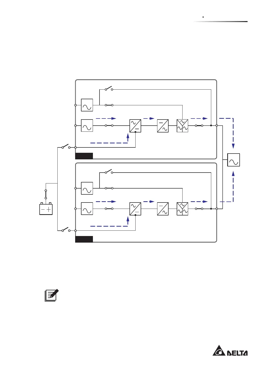
3.10 Common Battery
To save on your costs and installation space, parallel UPSs can share external battery cabi-
nets. In common battery mode, please install an isolated switch between each UPS and its
connected battery cabinets. Please see Figure 3-10 for two parallel UPSs sharing one ex-
ternal battery cabinet.
(Figure 3-10: Path of Electrical Power through the Parallel UPSs in Common Battery Mode)
UPS 1
LOAD
UPS 2
BYPA.
MAIN
BYPA.
MAIN
Circuit
Breaker
Batteries
Q3 Switch
Q2 Switch
Q1 Switch
Rectifier Inverter
STS
Q4 Switch
Q3 Switch
Q2 Switch
Q1 Switch
Rectifier Inverter
STS
Q4 Switch
If parallel UPSs share external battery cabinets, you should use the control panel to set up
‘TYPE(AH)’, ‘BAT STRINGS’, ‘FLOAT CHARGE VOLT(V)’, ‘BOOST CHARGE VOLT(V)’,
and ‘CHARGE CURRENT(A)’. Please refer to 8.7.3 Battery Setup and 8.7.4 Charger
Setup.
NOTE:
3OHDVHQRWHWKDW\RXVKRXOGVHWHDFK836ÀRDWYROWDJHGHIDXOW9WKHVDPH
each UPS boost voltage (default: 288V) the same, and set each UPS charge
current even. For example, when two UPSs are paralleled, they share one battery
cabinet, battery type is 120AH, and you want to set the battery cabinet’s charge
current as 20A. You should set each UPS ‘TYPE(AH)’ as 60AH, ‘BAT STRINGS’ as
1, and ‘CHARGE CURRENT(A)’ as 10A.