5-4
Ultron DPS Series
5.3 Fixing the UPS
Please follow the steps below:
1
%HIRUH¿[LQJWKH836LQDGHVLJQDWHGDUHDSOHDVHGRXEOHFKHFNZKHWKHUWKHDUHD¶V
ÀRRUZHLJKWORDGLQJLVVXI¿FLHQWWREHDUWKH836DQGH[WHUQDOEDWWHU\FDELQHWVWRDYRLG
accidents. Please refer to Table 5-1.
2
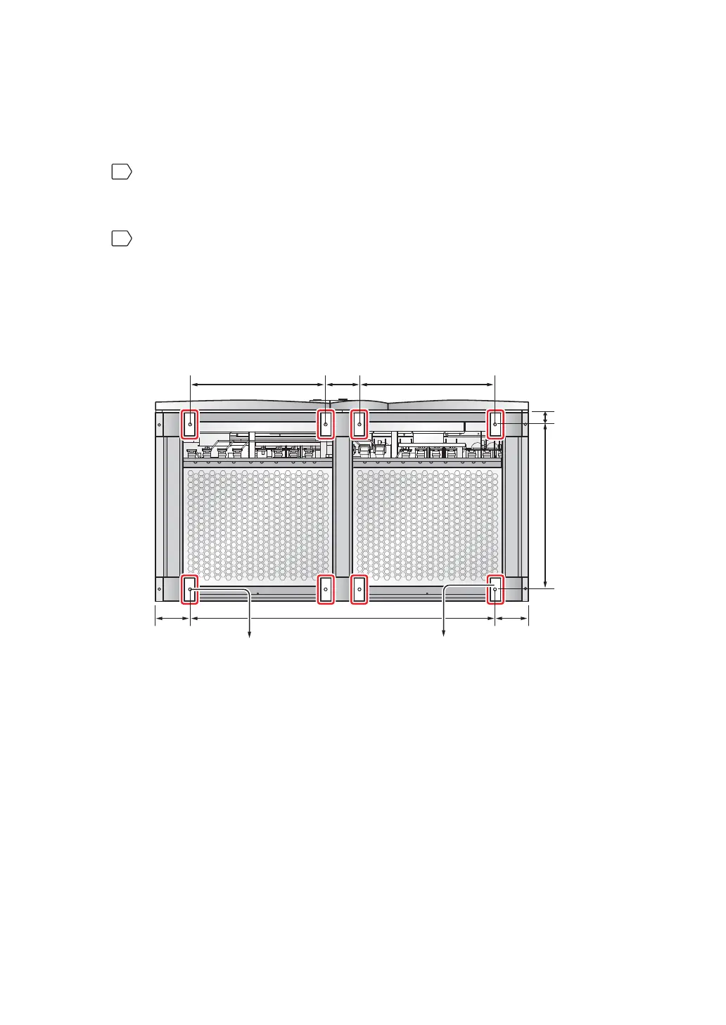
There are eight balance supports locating at the front bottom and the rear bottom
RIWKH8363OHDVHXVHDPPEXVKLQJWRRODQGHLJKWH[SDQVLRQVFUHZVWR¿[WKH
UPS’s eight balance supports on the ground; please refer to Figure 5-2: Mounting
Hole Dia-gram and Figure 5-3: Balance Support Installation. Please note that
service person-nel should provide the expansion screws.
(Figure 5-2: Mounting Hole Diagram)
(Front of the UPS)
Balance
Supports
580.8 mm580.8 mm 145 mm
146.7 mm
50 mm 707.6 mm
146.7 mm 1306.6 mm
(Rear of the UPS)
Mounting Hole
(Diameter: 13 mm)