5-13
5
Installation and Wiring
6
Follow UPS model No. to select appropriate input/ output cables. Please refer to
Table 5-2.
7
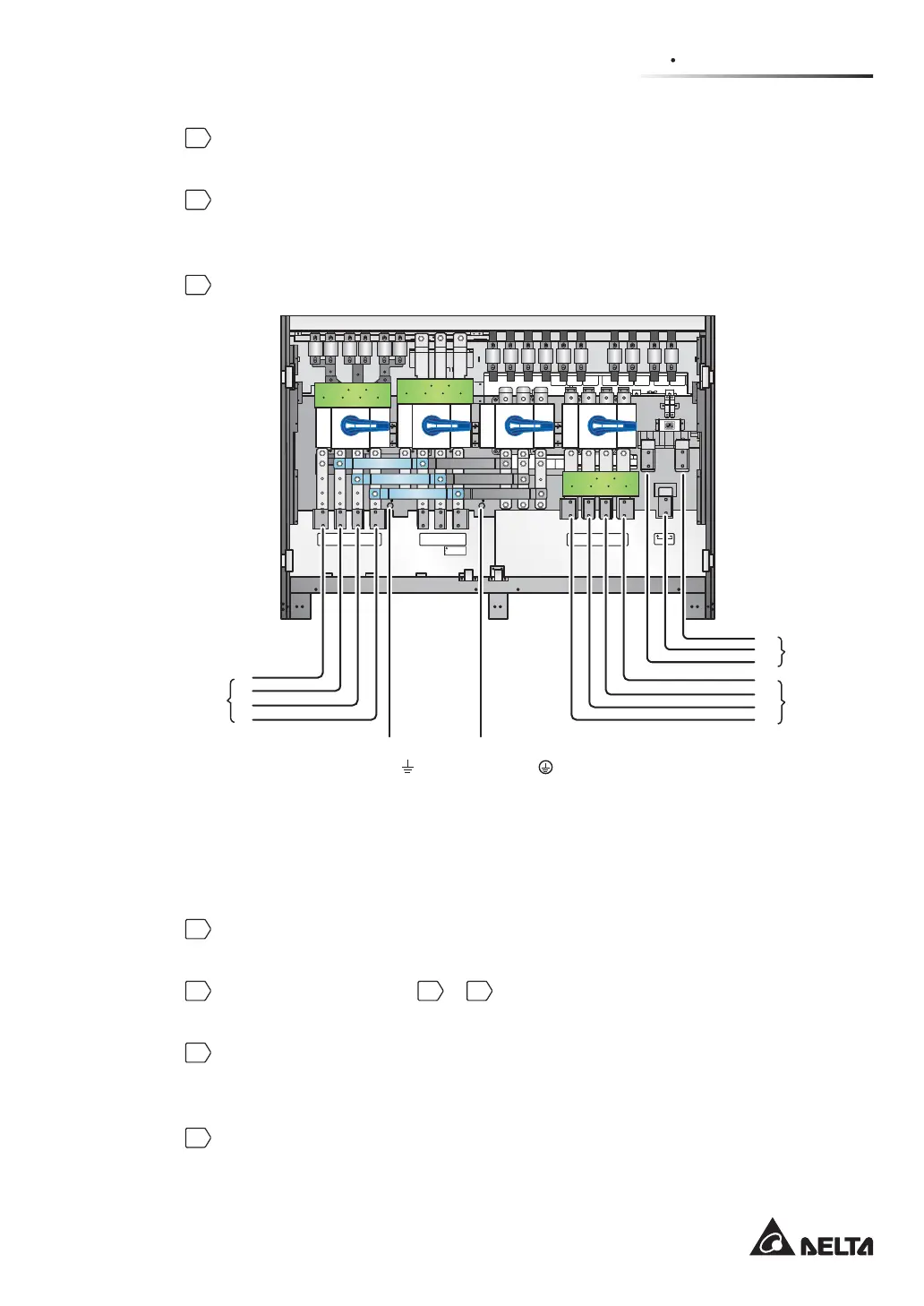
Connect the main AC source/ UPS output/ external battery cabinet cables to
the wiring terminal block. Please refer to Figure 5-12 and 5.5 External Battery
Cabinet Connection Warnings.
8
Ground the UPS.
(Figure 5-12: Single Unit Single Input Wiring Diagram)
O OFF
ON I
O OFF
ON I
O OFF
ON I
O OFF
ON I
Isolate Uninterruptible Power System (UPS)
Then check for Hazardous Voltage between all
terminals including the protective earth
See installation instructions before connecting to the supply
Apparatet er egnet for tilkopling til et IT forsyningsnett
RISK OF VOLTAGE BACKFEED
BEFORE WORKING ON THIS CIRCUIT
T
SR
N
UPS O UTP UT
TSRN
AC INPUT
R
S
T
BYPASS IN PUT
240VD C240VDC
BATTERY INPUT
N
Main
AC
source
External
battery
cabinet
UPS
output
For the critical
loads’ grounding( )
For the UPS
grounding( )
T
S
R
N
-
N
+
N
R
S
T
y
Dual Input (Single Unit)
When there are two AC power sources, single unit wiring procedures are as follows.
1
Follow 6LQJOH,QSXW'XDO,QSXW0RGL¿FDWLRQ to modify the UPS into dual
input.
2
Refer to the procedures
1
~
6
stated in the section of Single Input (Single
Unit).
3
Connect the main AC source/ bypass AC source/ UPS output/ external battery
cabinet cables to the wiring terminal block. Please refer to Figure 5-13 and 5.5
External Battery Cabinet Connection Warnings.
4
Connect the bypass source’s neutral to the neutral (N) terminal of the AC Input
Block.