7-14
Ultron DPS Series
y
Parallel Switch Operation Warnings
1. UPSs only with the same capacity, voltage and frequency can be paralleled.
2. If you want to parallel UPSs (at maximum eight), you should use the control panel to
set each UPS’s parallel group ID No. and parallel ID No. Please see 8.7.5 Parallel
Setup.
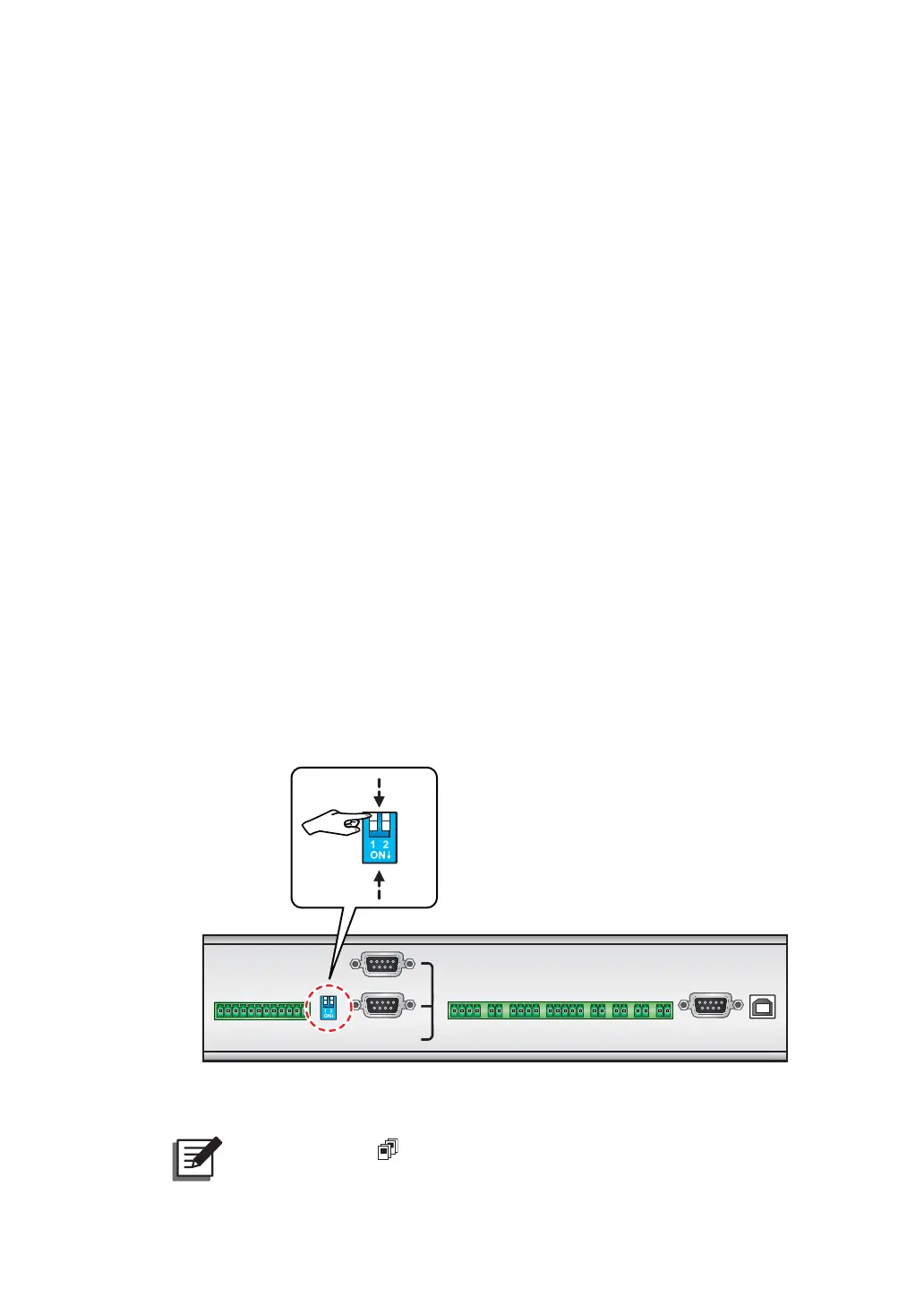
3. When paralleling UPSs, you should set up the parallel switch marked in the circle
shown in Figure 7-3. The parallel switch includes two DIP switches. To turn on a
DIP switch, set the DIP switch to the down position. To turn off a DIP switch, set the
DIP switch to the up position.
1) When two UPSs are paralleled, turn on each UPS’s DIP switches.
2) When three UPSs are paralleled, turn off the middle UPS’s DIP switches and turn on
the remaining UPSs' DIP switches.
3) When four UPSs are paralleled, turn off the middle two UPSs’ DIP switches and turn
on the remaining UPSs’ DIP switches.
:KHQ¿YH836VDUHSDUDOOHOHGWXUQRIIWKHPLGGOHWKUHH836V¶',3VZLWFKHVDQG
turn on the remaining UPSs’ DIP switches.
5) When six UPSs are paralleled, turn off the middle four UPSs’ DIP switches and turn
on the remaining UPSs’ DIP switches.
:KHQVHYHQ836VDUHSDUDOOHOHGWXUQRIIWKHPLGGOH¿YH836V¶',3VZLWFKHVDQG
turn on the remaining UPSs’ DIP switches.
7) When eight UPSs are paralleled, turn off the middle six UPSs’ DIP switches and turn
on the remaining UPSs’ DIP switches.
RS-232
USB
PARALLEL
OUTPUT
DRY CONTACT
C1 C2 C3 C4 C5 C6
P1 P2 P3 P4 P5 P6 P8P7
ON
OFF
(Figure 7-3: Set up the Parallel Switch)
NOTE:
The icon shown in the LCD diagrams means that the UPS is in
parallel mode.