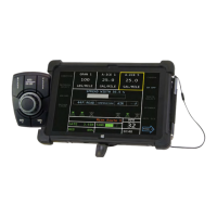
OPERATOR’S MANUAL
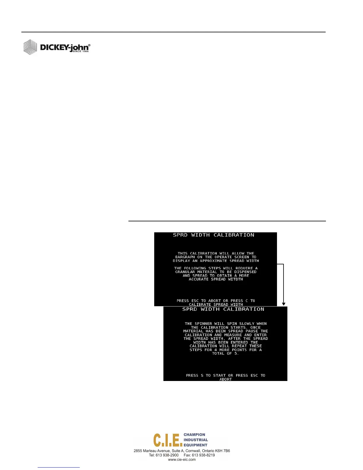
SPINNER SPREAD WIDTH
A spinner spread width calibration adjusts to the spinner configuration
settings defined at the Spinner Calibration screen and correlates these
settings to the increase and decrease adjustment of the spread width knob
automatically adjusting the amount of material applied. A spread width bar
graph displays on the Operate screen to indicate spread width percentage.
IMPORTANT: A spinner spread width calibration can only be
performed when spinner units are selected as feet on
the Spinner Configuration (F4) screen.
To perform a Spinner System Response Calibration:
1.
Load vehicle with material.
2.
At the F6 Calibration menu, select Spinner Spread Width and follow
onscreen instructions.
3.
Position a suitable container to catch all granular material dispensed
from the conveyor/auger. The larger the sample weighed, the better
the accuracy. The container must be large enough to obtain a good
representative sample.
4.
Press C to proceed to further calibration instruction.
5.
Press S to start calibration.
Figure 99
Spinner Spread Width
6.
When a sufficient amount of material has dispensed, press “C” to
pause the calibration.
7.
Measure the material dispensed and enter the spread width amount in
inches into the Spread Width popup window. This process is required
an additional 4 times to calculate an average that appears on the
screen each time another calibration is ran.
114 / CALIBRATIONS
Flex4 Pro
TM
Control System
6010541 Rev A