OPERATOR’S MANUAL
ACCESSORY SENSORS (F9)
Accessory sensor screen sets the parameters for installed sensors that can
be monitored, when enabled, on the Operate screen. All accessory sensors
are set to disabled and must be enabled and may require calibration.
Up to four analog sensors can be enabled at one time. Analog sensor types
include:
•
Gate height
•
Bed height
•
Road/Air temperature (requires the Flex4 interface cable and
RoadWatch temperature adapter that connects to any of the analog
1-4 positions on the rate control module harness.
•
Tank level
•
Down pressure
Two digital accessory sensors can be enabled at one time.
In addition to configuring accessory sensors, an installed DICKEY-john
joystick’s active position can be viewed on the Operate screen when
enabled at this screen.
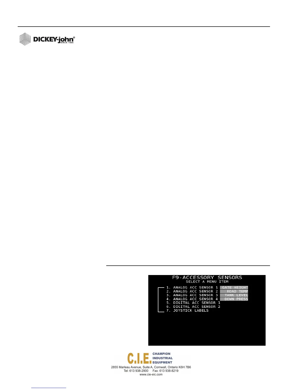
To enable Accessory Sensors:
1.
At the (F9) Accessory menu screen, highlight the Analog Acc Sensor
input box and press the Enter key to open the sensor drop down list.
2.
Select the sensor and press Enter.
3.
To open the Sensor Configuration screen of the selected sensor, press
the corresponding key (1 - 6) to select a menu item. Refer to
(Figure 64).
IMPORTANT: The RoadWatch Sensor adapter must be connected to
an additional adapter cable that connects to the Rate
Control Module harness. The adapter cable must be
connected to the connectors labeled as Analog 1, 2, 3 or
4 . The connection point for the road temperature and air
temperature must be identified at the F9 Accessory
Sensor screen.
Figure 64
Accessory Sensors Screen
Press1‐7onkeyboard
toenableand
configurerespective
sensors.
72 / SYSTEM PROGRAMMING
Flex4 Pro
TM
Control System
6010541 Rev A