OPERATOR’S MANUAL
3.
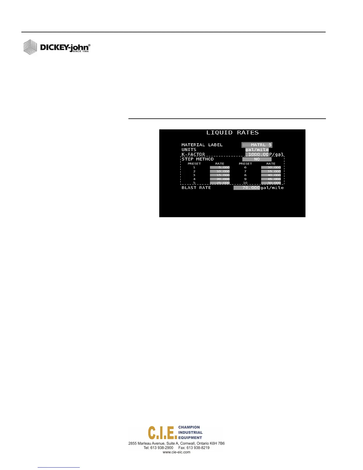
Enter desired rates (Rates 1-10). If less than 10 rates are desired,
enter a zero (0) for each rate following the last programmed rate. The
initial rate displayed during operation is Rate 1. Other rates are
selected by pressing the Rate Increase/Decrease button on the
switch module.
4.
Enter a desired blast rate that applies a higher-than-normal, spot
application when the Blast button is pressed during operation.
Figure 59
Rate Method Enabled
BOOM CONFIGURATION (LIQUID/ANTI-ICE)
Boom Configuration screen identifies how the unit is controlling or
monitoring boom sections and assigns boom sections to a liquid or auxiliary
channel. A total of 6 boom sections can be controlled by the system. A
DICKEY-john output module must be installed to support boom control.
To assign Boom Sections:
1. At the (F3) Liquid Menu screen, select 6 on the keyboard to display
the Boom Configuration screen.
1.
Select the function type as either Control or Sense.
2.
Select the active level output signal as either Ground or 12V.
3.
To change the default name for each boom label, press the respective
number (1-6) and type the new label name in the virtual keypad.
4.
Add the width of each boom section.
5.
Select the channel type that controls each boom label.
66 / SYSTEM PROGRAMMING
Flex4 Pro
TM
Control System
6010541 Rev A