Control|24 Guide18
Stereo Monitoring Connections
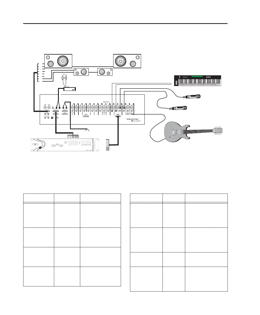
Figure 2 shows connections for a basic stereo configuration.
A Control|24 installation similar to that shown in Figure 2 requires the following connections.
Control|24 Inputs Contro|24 Outputs
Figure 2. Control|24 input and output connections for stereo mixing
MONITOR
L
R
to PRO TOOLS
from AUX OUT L R
LR
Cue mix
OUT
1
2
7
8
Pro Tools Out 1–2
MONITOR IN
to Pro Tools Inputs 1–8
D.I ch 1
to MIC in
to line in 5–6
SPEAKERS
Pro Tools
cue outs
3–4
Input connections for a simple stereo setup
Connector Channels Connects to
PRO TOOLS
MONITOR IN
25-pin D-Sub
1–2 Pro Tools audio
interface outputs,
main left/right mix,
for monitoring
AUXILIARY IN
TRS
left/right Pro Tools audio
interface outputs,
for cue mixing
MIC/LINE
Inputs
XLR, TRS
1–8, 9–16 Microphones and
other sources to
the mic preamps
EXTERNAL
SOURCES IN
25-pin D-Sub
1–8
optional
CD, DVD, other
sources for monitor-
ing and recording
Output connections for a simple stereo setup
Connector Channels Connects to
MONITOR
SPEAKERS
OUT
25-pin D-Sub
1–2 Main control room
speakers/monitors
MONITOR
SPEAKERS
OUT
25-pin D-Sub
7–8 Alternate control
room speak-
ers/monitors
AUX OUT
TRS
AUX OUT
left/right
Cue mix system
inputs
LINE
OUTPUTS
25-pin D-Sub
1–8,
9–16
Pro Tools audio inter-
face inputs for
recording mic
preamp sources