Control|24 Guide30
5.1 Track Layouts, Routing, and Metering
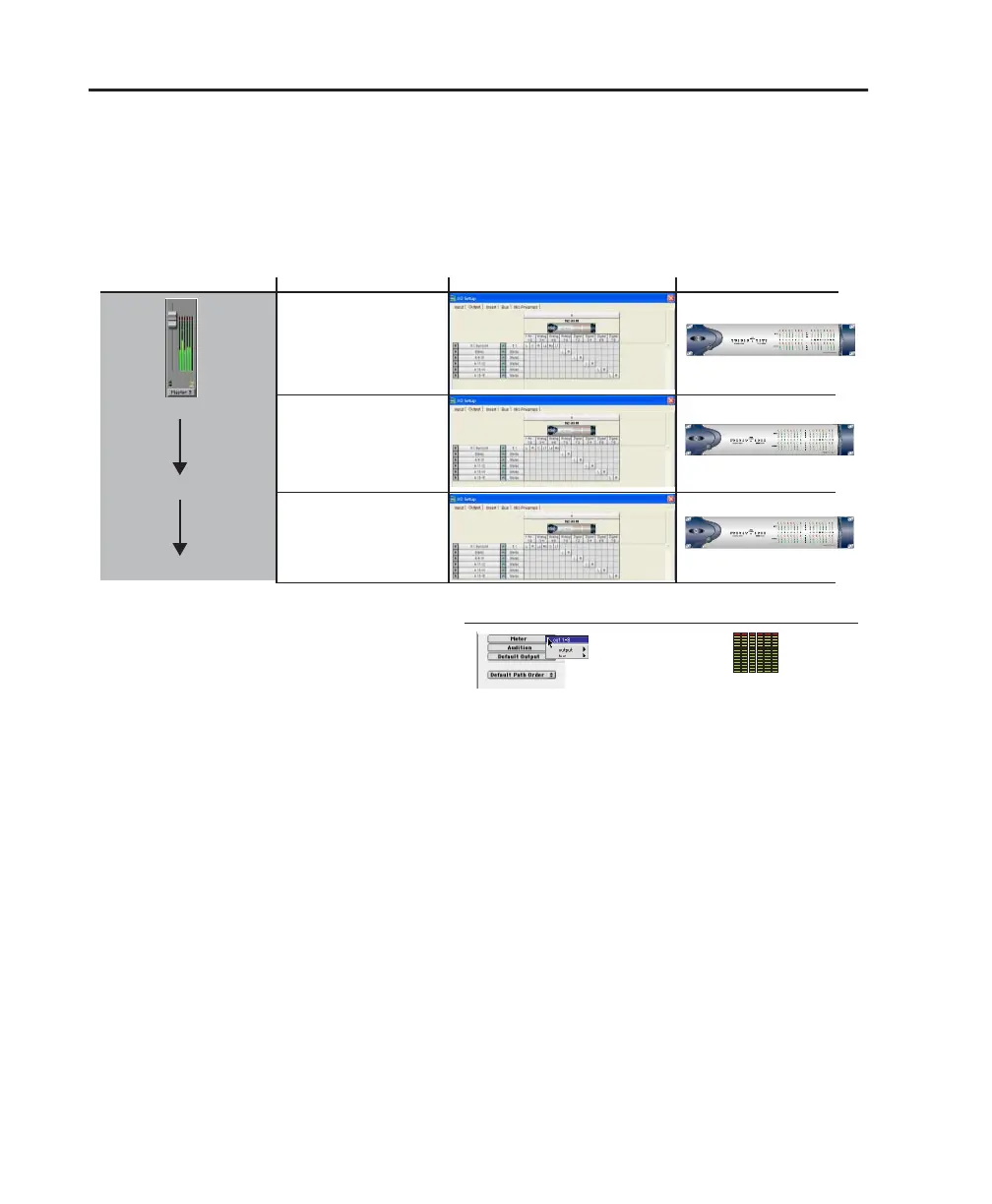
Figure 5 shows the relationship between Pro Tools I/O Setup configurations, audio interface and
channel meters when mixing in 5.1. Pro Tools on-screen 5.1 meters are always mapped according to
the Film standard L, C, R, Ls, Rs, LFE. Output meters on Control|24 and Pro Tools audio interfaces,
however, follow channel mapping in I/O Setup.
Figure 5. Track Layout and metering of different 5.1 formats in Pro Tools
Audio Interface Meters
Track Layout in I/O Setup5.1 Path Format
Film (Pro
Tools Default)
SMPTE/ITU
DTS (ProControl Default)
L C R Ls Rs LFE
L R Ls Rs C LFE
L C
L R
L R
C LFE Ls Rs
R Ls Rs LFE
Ls Rs C LFE
Default Meter Path
Control|24 Output Meters
same
same
L C R Ls Rs LFE
Pro Tools Tracks, Meters
Control|24 Output Meters match the Default Meter Path
L R C LFE Ls Rs
for Dolby Digital (AC3)
(Control|24 Default)