Control|24 Guide66
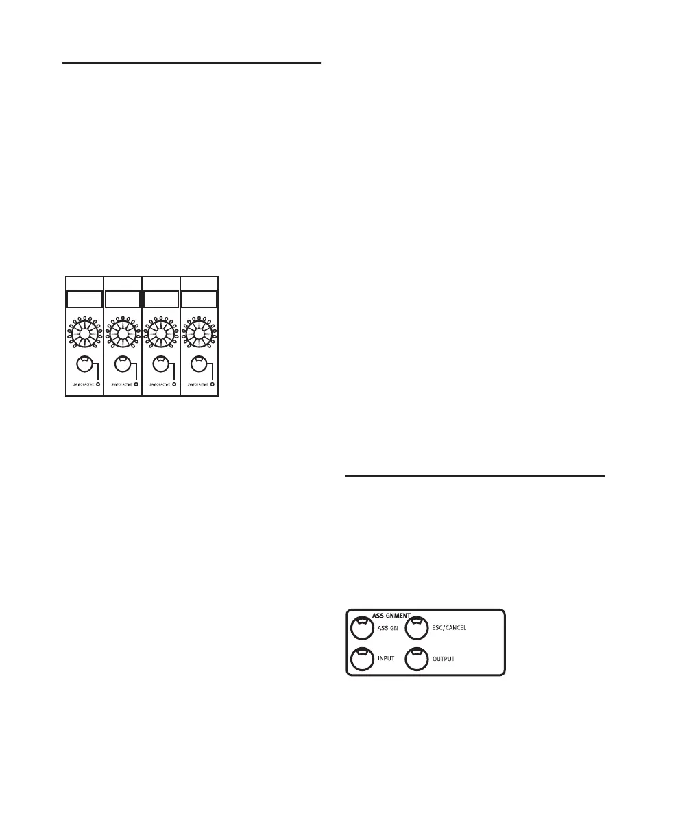
Data Encoder and LED Rings
Directly below the scribble strip on each chan-
nel is a Data Encoder knob (surrounded by a
ring of 15 LEDs). In conjunction with the Chan-
nel Bar Display and scribble strips, the Data En-
coder Knobs and LED indicators are used to dis-
play and adjust values and parameters.
Depending on mode configuration, these knobs
perform a variety of functions, some of which
can take advantage of velocity sensitivity mode.
The Data Encoder Knobs function by default as
pan controls. The LED ring around each knob
give you a visual approximation of the pan set-
tings for each channel. When an encoder knob
in Pan mode is moved, its precise setting is mo-
mentarily displayed in the scribble strip directly
above.
Fine Adjust Mode
To adjust channel pan, send level or (stereo) send
pan with Pro Tools fine-adjust mode:
■ Press (CTL) while adjusting pan or send
level.
Velocity Sensitivity
By default, the data encoders are in a fixed-ve-
locity mode, that emulates the feel of analog
pots. The VEL SENS ENCODERS switch globally
toggles the encoders to a velocity-sensitive
mode in which fine adjustments can be made
with greater precision by turning the knobs
more slowly.
To enter velocity-sensitive mode:
■ Press the VEL SENS ENCODERS switch. After
pressing VEL SENSE ENCODERS, a message will
be displayed briefly across the scribble strips:
“Channel encoders are now in velocity sensitive
mode.”
To return to the default non-velocity-sensitive
mode:
■ Press the VEL SENS ENCODERS switch again.
The message “Channel encoders are now in
fixed mode” will be displayed briefly across the
scribble strips.
INPUT and OUTPUT Switches
The INPUT and OUTPUT switches in the Assign-
ment section work in conjunction with the en-
coder knobs and scribble strips on each channel
to assign input and output routing. See “Assign-
ing Channel Input” on page 87.
Data Encoder and LED Rings
Dvrb Dvrb Dvrb Dvrb