Dobot M1 User Guide 3 Hardware Installation
Issue V1.3.4 (2019-05-23) User Guide Copyright © Yuejiang Technology Co., Ltd
22
NOTE
The appearance of the air pump depends on the production batch of Dobot M1. However,
the connection method remains unchanged.
Table 3.1 Cable Description
OUT1: Control the intake and outtake of the air pump
OUT2: Control the status of the air pump
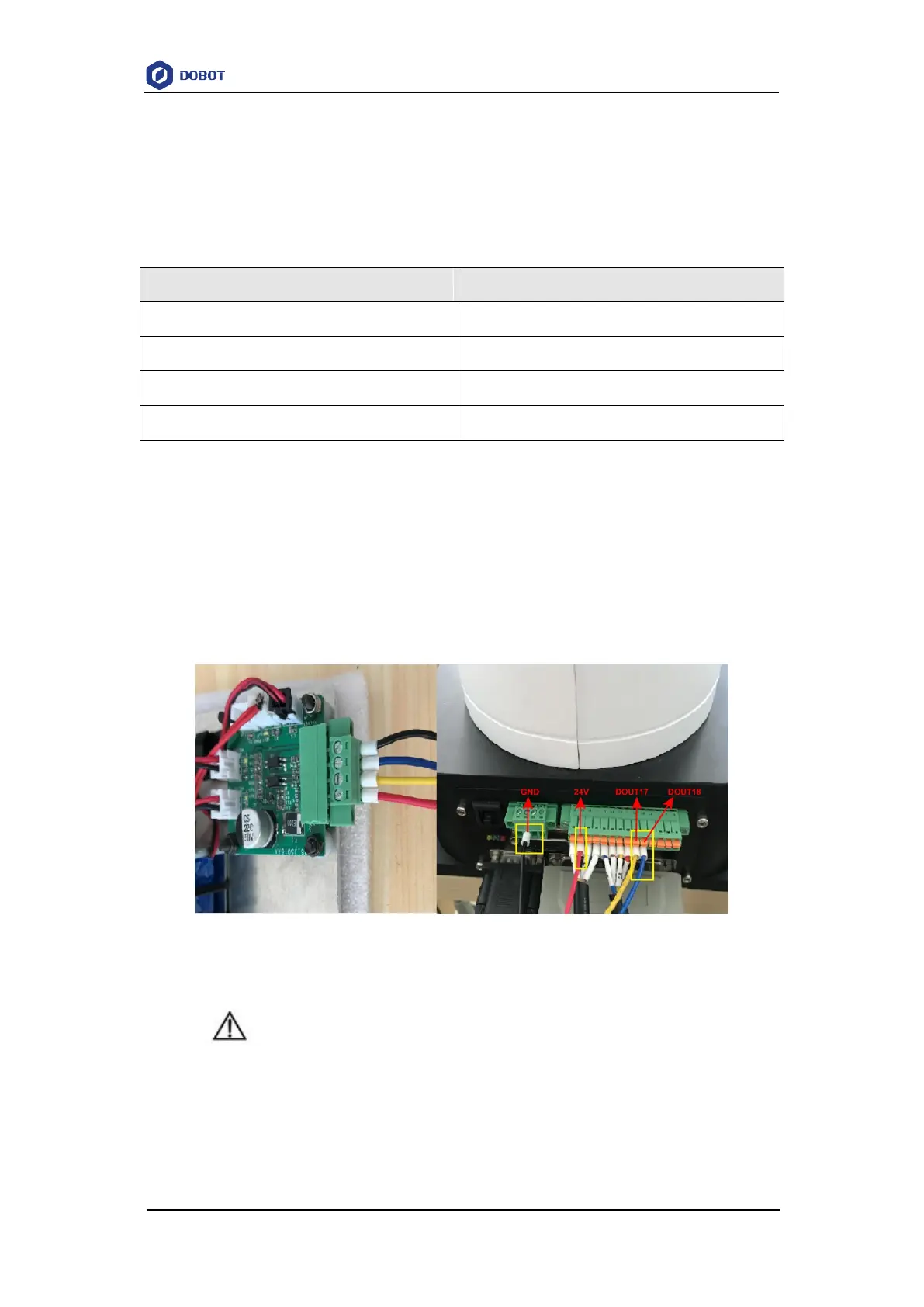
If the air pump is connected to the base I/O interface. The yellow cable and the blue one are
connected to the output pins (The corresponding outputs listed in 4.3.2.2 Base I/O Interface are
DOUT17 and DOUT18) of the base I/O interface. The red one and the black one are connected to
the VCC_24V pin on the base I/O interface and the PGND pin on the CAN bus interface
respectively, as shown in Figure 3.10, and you need to tighten them with a straight screwdriver. The
description in this topic is for reference only. Please choose the appropriate interface to connect the
air pump. For details, please see 4.3 Interface Description.
Figure 3.10 Air pump connection
NOTICE
When an air pump is connected to I/O interface, the terminals of air pump cannot be
exposed to the air, to avoid short circuit. If that happens, you need to cut them to an
appropriate length. For matching all I/O interfaces, terminals of air pump will be slightly
longer. Figure 3.11 and Figure 3.12 show the standard and non-standard connection of
the terminals respectively.