APPENDIX B : A--SERIES AIR DRIVEN AIRDRYER
B--18 20951 Issue 1 Apr 98
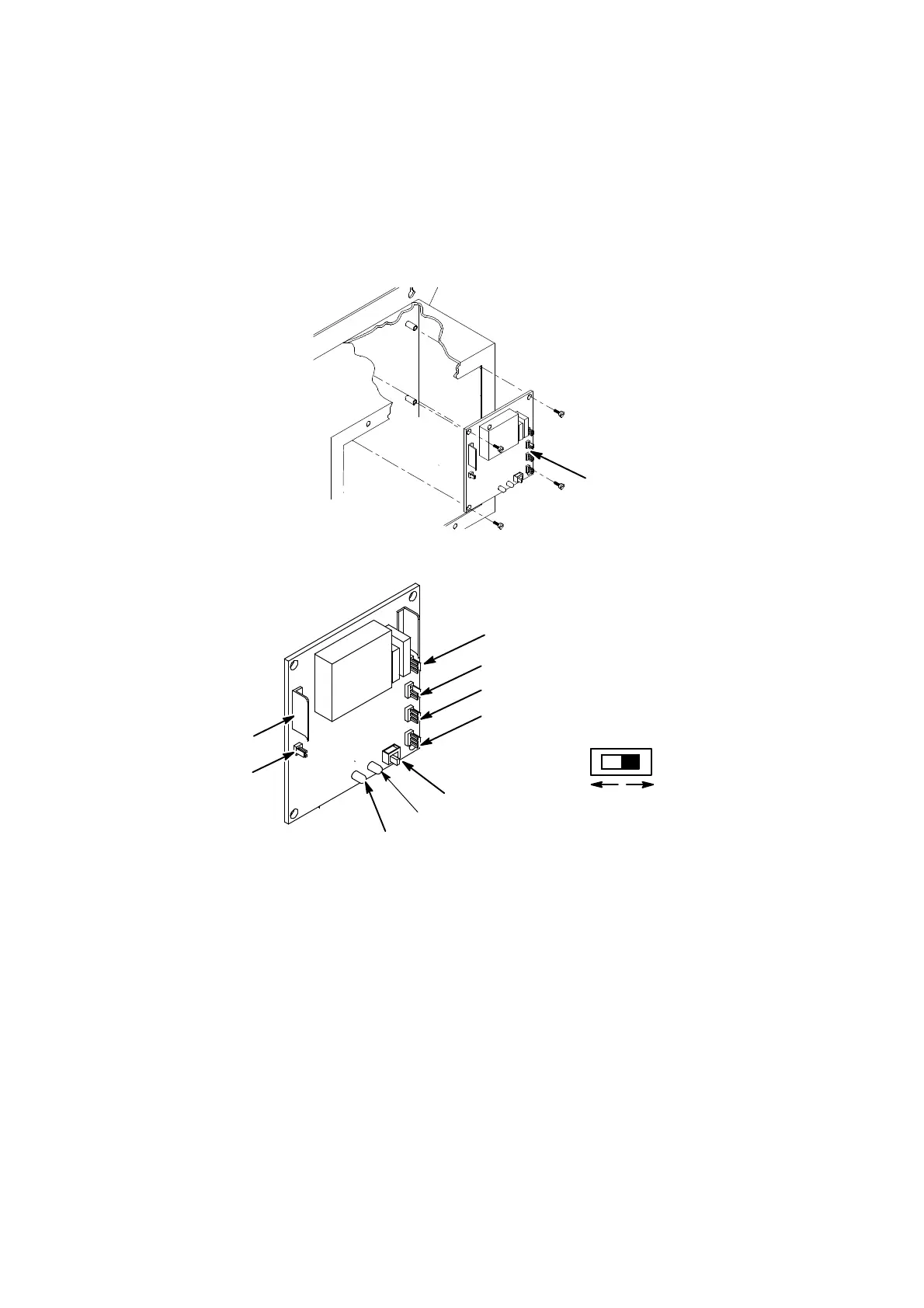
PCB Removal and Replacement
WARNING: Power to the printer must be removed.
CAUTION Always use anti--static procedures when handling
PCBs or integrated circuits.
The cover must be removed.
Printed Circuit
Board
Printed Circuit Board Removal
TP7225--3
Sounder
Printed Circuit Board Connections
Fault Lamp
Power Indicator
Pressure Switch
SW1 Mode Switch
LED2 Humidity Indicator
LED1 Power indicator
Power Input
Humidity
Sensor
Normal
Bypass
TP7225--3
(1) Remove the securing screws and PCB cover.
(2) Note orientation of all connectors and remove from PCB.
(3) Remove the nylon securing screws and lift out the PCB.
To replace the PCB:
(4) Fit the PCB into the housing and secure with the nylon screws.
(5) Re--connect the cables to the PCB connections noted in step 2.
(6) Refit and secure the cover over the PCB.

 Loading...

