106
x Scanner Section
chap.3
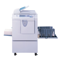
(6) Removal of Slider A
1. Perform steps 1 through 4 of procedure (4).
2. Loosen the 2 screws shown, and remove slider A.
\See page 104
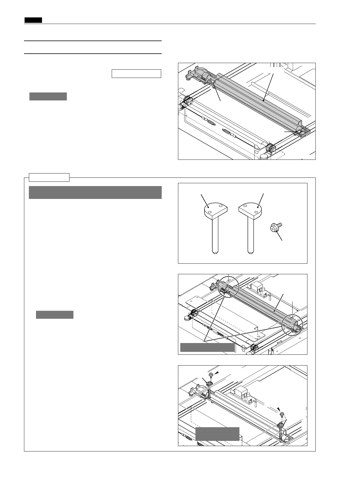
Reinstallation
¡ Required items
2 Slider A attachment tools
4 Set screws
Do not move Slider A by hand.
IMPORTANT :
1. Move the slider A by rotating the timing pulley
to align the frame holes with the slider A posi-
tioning holes. (See the figure on the right.)
2. Set the 2 slider A attachment tools and attach
the 4 set screws.
3. Fix the wire with 2 screws.
4. Remove the 2 slider A attachment tools.
Do not move Slider A by hand.
IMPORTANT :
R8S03023
Screw
R8S03026a
Slider A attachment tool
Set screw
R8S03024a
R8S03025a
Slider A
Align holes positions
Slider A
Screw
Slider A attachment tool
Set screw
Set screw
Attachment
tool
Attach-
ment tool
Insert the tool to
fix the wire.
¡ Attach the slider B first and then slider A.
 Loading...