Cause/Detective section
Procedures
Result
CountermeasureItems to be checked
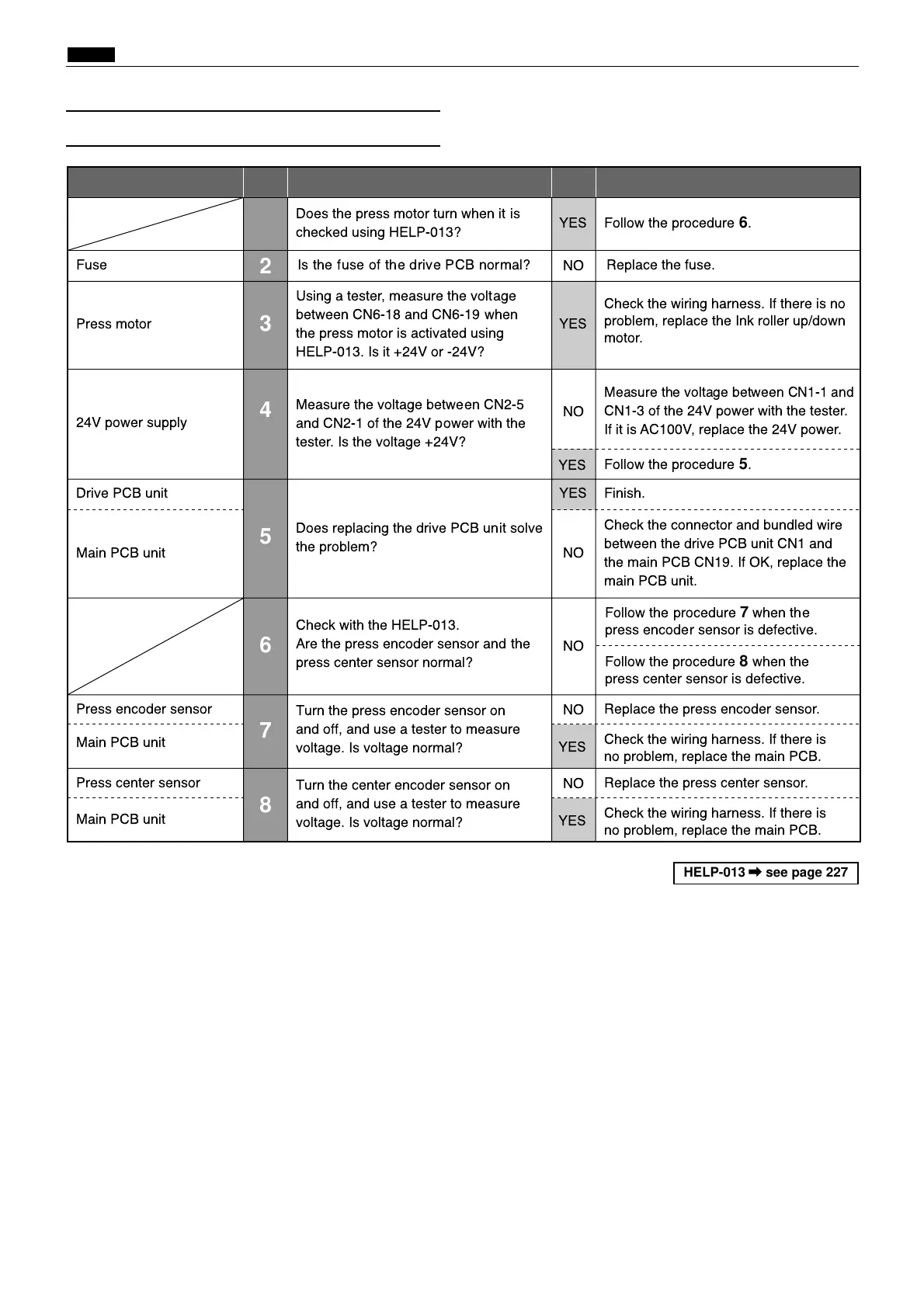
1
Does the press motor turn when it is
checked using HELP-013?
YES Follow the procedure
6
.
Press motor
3
Using a tester, measure the voltage
between CN6-18 and CN6-19 when
the press motor is activated using
HELP-013. Is it +24V or -24V?
YES
Check the wiring harness. If there is no
problem, replace the Ink roller up/down
motor.
Drive PCB unit
5
6
Does replacing the drive PCB unit solve
the problem?
YES Finish.
Main PCB unit NO
NO
Check the connector and bundled wire
between the drive PCB unit CN1 and
the main PCB CN19. If OK, replace the
main PCB unit.
Main PCB unit
Press encoder sensor
7
Turn the press encoder sensor on
and off, and use a tester to measure
voltage. Is voltage normal?
Turn the center encoder sensor on
and off, and use a tester to measure
voltage. Is voltage normal?
NO
Replace the press encoder sensor.
Check the wiring harness. If there is
no problem, replace the main PCB.
Follow the procedure
5
.
YES
YES
Main PCB unit
Press center sensor
NO
Replace the press center sensor.
Check the wiring harness. If there is
no problem, replace the main PCB.
YES
8
24V power supply
4
Measure the voltage between CN2-5
and CN2-1 of the 24V power with the
tester. Is the voltage +24V?
NO
Measure the voltage between CN1-1 and
CN1-3 of the 24V power with the tester.
If it is AC100V, replace the 24V power.
Fuse Is the fuse of the drive PCB normal? Replace the fuse.
2
NO
Check with the HELP-013.
Are the press encoder sensor and the
press center sensor normal?
Follow the procedure
7
when the
press encoder sensor is defective.
Follow the procedure
8
when the
press center sensor is defective.
 Loading...