161
, Electrical system
chap.4
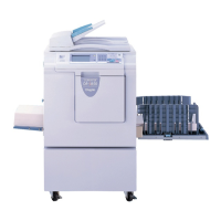
(3) Reading Start Position
1. Mark with 1mm interval up to 5mm from the top
end of the paper to prepare a test document.
2. Perform master making and printing to the same
size and to two printouts.
3. Make adjustment by "3. SCAN LEAD EDGE
START POSITION" of HELP-042 so that printing
starts at 2 mm from the document lead edge on
the second print paper.
HELP - 042 \ see p.245
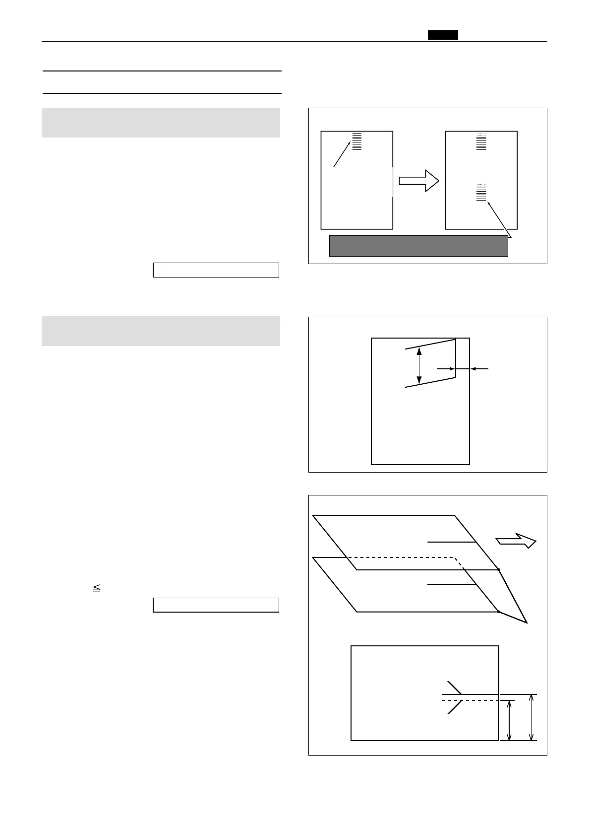
Adjustment procedure
1. Make a basic document (as shown in the figure)
from a sheet of paper*.
Draw a 100mm line at the position 30mm from
the right end and from the top end of the paper*.
*DP-S850/S650/S550 : A3 paper
*DP-S620/S520/S510 : B4 paper
2. Compare the printed image with the basic
document.
Check the difference between the straight lines
in the vertical direction.
3. Adjust with the HELP - 042 so that
L1 - L2 ±3mm.
Adjusting direction
¡L1 < L2 : The value is decreased.
¡L1 > L2 : The value is increased.
HELP - 042 \ see p.245
¡Basic document
30mm
100mm
Print
Mark with 1mm
interval from the top
end of the document
Mark this corner
with each other
Document basic line
L2 L1
Document
Printing paper
Print ejection
direction
Basic line of the printed sample
2 printouts
Document
23S0313
23S0314
23S0315
1. Adjusting the Top End Reading Start Position
Adjustment procedure
Make sure that the second printing starts
at 2 mm from the document lead edge.
2. Adjusting the Lateral (Operation Side) Reading
Start Position
 Loading...